
100m 750kV UHV River Crossing Lattice Tower - 2-Circuit Long-Span Structure
Key Features
- 100m tower height engineered for 750kV UHV river and valley crossings with 1000m design span
- 2-circuit configuration with 6× ACSR-720 bundle conductors per phase for high-capacity transmission
- Heavy galvanized steel lattice structure designed to IEC 60826, GB 50545, IEEE 738, and ASCE 10-15 principles
- Grounding target below 10 ohms standard and below 4 ohms for high-lightning-density sites
- EPC turnkey pricing from $350,000 to $480,000 including engineering, installation, commissioning, and 1-year warranty
The 100m 750kV UHV River Crossing Lattice Tower is a heavy steel lattice transmission structure engineered for 2 circuits, 6-bundle ACSR-720 conductors per phase, and a 1000m design span across rivers, valleys, and navigable waterways. Built to IEC 60826, GB 50545, IEEE 738, and ASCE 10-15 principles, it supports high mechanical tension, navigation clearance, OPGW integration, and 50-year service life for utility-grade EPC projects.
Description
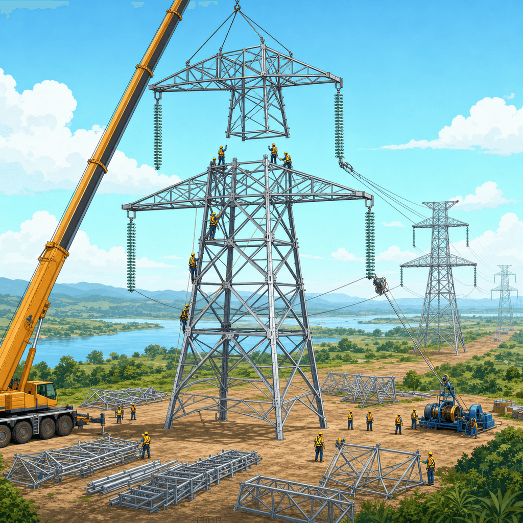
The 100m 750kV UHV River Crossing Lattice Tower is a utility-scale 2-circuit transmission structure designed for 750kV ultra-high-voltage service, 100m tower height, 1000m design span, and 6× ACSR-720 bundled conductors per phase. This river-crossing configuration uses heavy galvanized steel lattice construction to manage high longitudinal tension, broken-wire conditions, navigation clearance, and wind/ice loading in demanding corridor environments. For EPC buyers evaluating long-span transmission assets above 500kV, this model is configured for river, estuary, valley, and navigable waterway crossings where clearance, stability, and electrical performance must be balanced over 50 years of design life.
Product Overview
In UHV transmission planning, river-crossing towers differ materially from standard suspension towers because they must support longer spans of 500m to 1500m+, higher conductor tension, and greater clearance envelopes for marine traffic, flood levels, and catenary sag. This 100m variant is optimized around a 1000m span and 2 circuits, allowing utilities to move approximately 1000MW to 1500MW per circuit depending on conductor temperature, line rating method, and system dispatch assumptions. According to IEEE 738 conductor thermal rating methodology and utility practice for EHV/UHV lines, bundled conductors reduce surface gradient and corona losses while improving ampacity and radio interference performance.
For procurement teams, the structure combines Q420/Q460-class galvanized steel members, heavy base geometry, anti-galloping provisions, aviation and navigation marking compatibility, and optional OPGW shield wire integration. The design basis aligns with IEC 60826 for loading and strength of overhead transmission lines, GB 50545 for transmission tower engineering practice, and ASCE 10-15 concepts for steel transmission structures. Utilities and EPC contractors can View all Power Transmission Tower/Pole products or Configure your system online for project-specific wind zones above 30m/s, ice thickness above 15mm, and site geotechnical classes.
System Architecture
A complete 750kV river-crossing tower system includes 1 main lattice tower body, 2 circuit cross-arm assemblies, 6 subconductors per phase, insulator strings sized for UHV creepage and mechanical load, 1 to 2 shield wire positions, grounding electrodes, and a reinforced foundation package. The 100m elevation is selected to preserve conductor clearance under maximum sag conditions at high operating temperatures, often 70°C to 80°C conductor temperature depending on utility rating policy, while also maintaining navigation and flood safety margins. In practical engineering terms, the tower is not a standalone steel product but a line-system node integrating structural, electrical, civil, and communications functions over a corridor that may exceed 1km in unsupported span.
The lattice format remains the preferred choice for many 500kV+ crossing projects because it offers lower steel mass per stiffness unit than many tubular alternatives at heights above 80m, while enabling modular fabrication, bolted transport, and field assembly. Compared with a conventional 40m to 60m inland suspension tower, a dedicated 100m river-crossing tower typically requires substantially higher leg loads, wider foundations, and stronger cross-arm geometry. In long-span applications, this configuration can reduce the number of intermediate structures by 20% to 40% versus shorter-span routing alternatives, although each structure has a higher unit EPC value.
Technical Specifications
The specified configuration uses steel_lattice_heavy construction for 2 circuits at 750kV, with 6× ACSR-720 conductors per phase and a 1000m design span. For utilities using ACSR family conductors, the steel-reinforced core supports high tensile loading over long spans while the aluminum layers carry the majority of current. Based on IEEE 738 principles, bundle arrangements of 4 to 6 subconductors are typical in UHV classes because they reduce electric field intensity, audible noise, and corona effects compared with smaller bundles. For river crossings, the mechanical design case is often more critical than pure electrical loading because conductor tension, wind swing, and broken-wire imbalance can govern member sizing.
The standard environmental template for this product is Class B wind / 15mm ice, but project-specific engineering can be extended to higher wind regimes, differential ice, seismic loading, and extreme temperature bands. Tower footing resistance is typically designed below 10 ohms, and in high-lightning-density areas below 4 ohms, to improve surge dissipation and shield-wire performance. The structure is compatible with porcelain or composite insulators, although many EPC clients now specify polymer long-rod units to reduce weight and maintenance over 30 to 50 years. For grounding, communications, and line monitoring, OPGW integration supports both lightning shielding and fiber backhaul in a single overhead element.
Structural Design Basis
A river-crossing tower at 100m height experiences a different load envelope from a standard line tower because the span of 1000m increases longitudinal tension and deflection sensitivity. The design process generally evaluates normal operation, maximum wind, ice plus wind, broken conductor, broken shield wire, erection condition, and maintenance load cases. Under IEC 60826, reliability-based loading methods consider return periods and consequence classes, while national utility specifications may apply additional factors for navigable waterways and strategic transmission corridors. In these projects, the foundation often controls both capex and schedule because uplift, compression, and overturning can be materially higher than on a 220kV or 400kV inland structure.
The heavy lattice arrangement also supports field logistics. Members can be hot-dip galvanized after fabrication and shipped in bundles for bolted erection, reducing transport complexity compared with very large monolithic sections. Galvanizing thickness and steel chemistry are selected to support corrosion performance over 25 to 50 years depending on atmosphere class, maintenance regime, and coating specification. For marine-adjacent or industrial river corridors, coating selection and inspection intervals are especially important because chloride deposition and humidity can accelerate corrosion rates. This is one reason many utilities still favor robust lattice geometries over lighter visual-profile concepts when crossing mission-critical waterways.
Electrical Performance and UHV Suitability
At 750kV, electrical clearances, corona control, and insulation coordination are central to tower selection. The 6-bundle ACSR-720 arrangement increases equivalent conductor diameter and reduces surface electric stress, which helps limit corona losses and radio interference under wet conditions. According to utility practice summarized by IEA and regional transmission operators, UHV and EHV corridors are used to move large blocks of power efficiently over hundreds of kilometers with lower resistive losses than lower-voltage alternatives carrying the same megawatt transfer. For a 2-circuit crossing tower, the line can serve generation evacuation, interconnection reinforcement, or cross-river backbone transmission where right-of-way options are limited.
Compared with a conventional 220kV or 330kV multi-tower crossing solution, a 750kV river-crossing design can transmit substantially more power per corridor width, often reducing the number of separate alignments and waterway interfaces required. In many utility studies, stepping from lower voltage classes to UHV/EHV can lower line losses by 20% to 30% for equivalent power transfer over long distances, though exact savings depend on conductor size, loading factor, and route length. This product is therefore most appropriate where high-capacity transfer justifies the larger foundation, tower steel tonnage, and insulator string cost.
Foundation and Civil Engineering
For a 100m river-crossing tower, the foundation is usually engineered as a reinforced concrete spread footing, pile-supported footing, or hybrid pile-cap system depending on geotechnical conditions. While the configuration template leaves the foundation type open for site design, long-span UHV crossings frequently require deep piles of 15m to 35m or more in soft alluvial soils, riverbanks, reclaimed land, or flood-prone zones. Concrete volumes can exceed 150m3 to 300m3 for a single structure depending on leg reactions, allowable bearing pressure, and uplift resistance. Soil resistivity testing, flood level analysis, and scour assessment are therefore mandatory inputs before final EPC pricing is frozen.
From a lifecycle perspective, foundation quality has direct impact on reliability over 50 years. Differential settlement of even a few millimeters can alter leg force distribution and affect tower geometry, especially in long-span crossings where conductor tension is high. Best practice is to complete geotechnical drilling, groundwater characterization, and topographic survey before final member detailing. Buyers planning a bank-to-bank crossing can Request a custom quotation with borehole logs, wind maps, and conductor data to receive a project-specific civil package within 1 to 3 weeks depending on complexity.
Corrosion Protection, Safety, and Maintenance
Hot-dip galvanized steel remains the dominant protection method for transmission towers because it offers durable zinc coverage and proven field performance. For a 50-year design life, maintenance planning normally includes visual inspection every 1 to 2 years, bolt-torque verification at defined intervals, grounding resistance measurement, and corrosion assessment in splash, industrial, or saline environments. Navigation lights and aviation markers are commonly added to towers above 60m, especially near airports, shipping lanes, or regulated waterways. These accessories should be specified at bid stage because power supply routing, mounting brackets, and maintenance access influence fabrication details.
Anti-galloping and spacer-damper provisions are also important for bundled conductors over long spans. In cold or windy regions, conductor oscillation can increase fatigue stress on fittings and towers if not controlled. Utilities often specify spacer dampers at intervals calculated from bundle geometry and aeolian vibration studies. Composite insulators can reduce dead weight by 20% to 40% compared with some porcelain string arrangements, which may simplify erection on tall crossing towers, although final selection depends on pollution class, utility standards, and maintenance preference.
Application Scenario
A grid developer in the MENA region planning a 750kV interconnection across a 900m navigable river selected a 100m heavy lattice crossing tower to preserve vessel clearance and avoid constructing 3 to 4 shorter structures inside the floodplain. By using 2 circuits with 6× ACSR-720 bundles and OPGW integration, the developer consolidated transmission capacity into a single crossing corridor and reduced right-of-way interfaces by approximately 30% compared with a lower-voltage multi-structure alternative. The EPC scope included geotechnical drilling to 28m, pile-cap foundations, navigation lighting, and commissioning in 11 months from notice to proceed.
In that scenario, the developer also compared the lattice solution with a conceptual tubular crossing structure. The lattice design was selected because it reduced fabrication risk, allowed containerized member transport, and lowered steel cost per installed meter by roughly 8% to 12% in the local supply chain. While tubular forms can offer visual benefits in some 400kV applications, heavy lattice remains the more common choice for 750kV long-span crossings where redundancy, field bolting, and maintenance familiarity are priorities.
Industry References and Engineering Context
This product category aligns with international transmission practice documented by IEC 60826 for loading, IEEE 738 for conductor thermal behavior, and ASCE 10-15 for steel transmission structures. For broader grid investment context, IEA reports continue to identify transmission expansion as a critical bottleneck for electrification and renewable integration, while IRENA highlights the need for high-capacity networks to connect remote generation resources to load centers. NREL and utility planning studies also emphasize that long-distance high-voltage transmission can improve system flexibility, reduce curtailment, and lower congestion costs when properly integrated with generation and demand growth. In procurement terms, these drivers support continued investment in 500kV to 800kV backbone lines and associated crossing structures.
For buyers evaluating design alternatives, it is useful to compare this product with lower-voltage crossings. A conventional 220kV tower may be sufficient for regional loads below several hundred megawatts, but once transfer requirements approach 1000MW+, the economics often favor higher-voltage corridors despite higher structure cost. The value proposition is not lower tower price; it is lower cost per delivered megawatt over the line life of 30 to 50 years. Additional background is available through Learn about topic and Learn about topic for tower selection, conductor choice, and EPC planning.
Applications
Typical applications include 750kV river crossings, estuary crossings, valley spans, port-access corridors, hydro-to-load interconnections, thermal plant evacuation, large renewable energy backbone lines, and cross-border grid links. In each case, the structure is intended for locations where a standard 40m to 80m line tower cannot maintain required clearance or mechanical reliability. The 100m profile is particularly relevant where navigation rules, flood levels, and conductor sag combine to demand large vertical clearance margins. Optional packages include aircraft warning spheres, obstruction lights, anti-climbing devices, additional shield wires, and utility-specific anti-corrosion systems.
For digital utility operations, the tower can also be specified with OPGW and line monitoring accessories such as vibration sensors, weather stations, or sag observation systems. These additions help operators manage conductor temperature, storm response, and maintenance scheduling across spans of 1km or more. In high-value corridors, remotely monitored assets can reduce unplanned outage risk and improve response time by several hours during severe weather events.
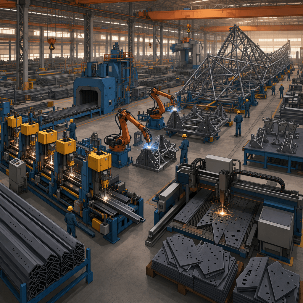
Procurement, Manufacturing, and Quality Control
Manufacturing of a tower in this class generally includes steel sourcing, CNC cutting, punching or drilling, trial assembly, hot-dip galvanizing, marking, packing, and dimensional inspection. For a project quantity of 10 to 50 towers, lead time is commonly 8 to 16 weeks for supply depending on final drawings, galvanizing queue, and shipping port schedule. Quality documentation can include mill certificates, galvanizing reports, bolt certificates, dimensional inspection records, and packing lists. For export projects, CIF logistics add freight and marine insurance, while EPC supply adds erection crews, cranes, foundation works, stringing coordination, and commissioning documentation.
Buyers should evaluate not only steel tonnage but also tolerances, bolt management, galvanizing quality, traceability, and site support. A low ex-works price can be offset by erection delays if member labeling or fit-up quality is poor. SOLARTODO supports utility and EPC procurement with configurable documentation, engineering coordination, and quotation support for projects ranging from 1 tower prototype supply to multi-structure crossing packages. For related products, View all Power Transmission Tower/Pole products, or Configure your system online to match voltage class, span, conductor bundle, and foundation concept.
EPC Investment Analysis and Pricing Structure
For this 100m 750kV river-crossing tower, EPC scope typically includes 5 major work packages: engineering, procurement, civil works, erection, and commissioning. Engineering covers structural calculation, shop drawings, foundation design adaptation, and QA/QC documentation. Procurement covers steel tower members, bolts, insulator hardware interfaces, grounding materials, and optional OPGW accessories. Construction includes excavation, concrete or pile works, tower assembly, lifting, tightening, grounding installation, and site restoration. Commissioning includes final inspection, as-built documentation, and handover, while the standard turnkey package includes a 1-year warranty.
| Pricing Tier | Scope | Price Range (USD) |
|---|---|---|
| FOB Supply | Equipment only, ex-works China | $217,000 - $326,400 |
| CIF Delivered | Equipment + ocean freight + insurance | $277,505 - $417,408 |
| EPC Turnkey | Engineering, supply, installation, commissioning, 1-year warranty | $350,000 - $480,000 |
For framework orders and utility programs, the following volume discounts are typically applied to the tower supply portion where project standardization is possible. Civil complexity, special coatings, and marine logistics may affect final discount realization.
| Order Volume | Discount |
|---|---|
| 50+ units | 5% |
| 100+ units | 10% |
| 250+ units | 15% |
A simplified ROI view compares this UHV crossing with building multiple lower-voltage crossings to achieve similar transfer capacity. If a utility avoids 1 to 2 additional crossing structures, reduces corridor interfaces by 20% to 30%, and lowers transmission losses by even 2% to 5% on a heavily loaded interconnection, the lifecycle economics can justify the higher capex within roughly 6 to 12 years depending on energy throughput and congestion value. Annual savings are highly project-specific, but on strategic corridors carrying high utilization, avoided losses and reduced maintenance interfaces can amount to tens of thousands of USD per year per crossing. Payment terms are typically 30% T/T + 70% against B/L, or 100% L/C at sight; financing support is available for projects above $1,000,000. Commercial contact: [email protected].
Buyer Guidance
This product is best specified when the project requires 750kV, 2 circuits, a span near 1000m, and a clearance-driven tower height of 100m. Before RFQ release, buyers should confirm 6 core inputs: conductor data, shield wire arrangement, design wind speed, ice thickness, geotechnical report, and navigation or aviation constraints. These six parameters determine most of the final steel weight and foundation cost. Early engineering alignment can reduce redesign cycles by 2 to 4 weeks and improve bid comparability across suppliers.
For budgetary planning, the turnkey range of $350,000 to $480,000 should be treated as a realistic EPC envelope for one tower under standard assumptions, not a substitute for a site-specific civil design. Soft soils, high seismicity, deep piles, marine barging, or accelerated schedules can move the final number upward. To receive a tailored proposal with GA drawings, loading assumptions, and commercial terms, Request a custom quotation.
Technical Specifications
| Tower Height | 100m |
| Voltage Rating | 750kV |
| Tower Type | river_crossing |
| Material | steel_lattice_heavy |
| Number of Circuits | 2circuits |
| Conductor Bundle | 6×ACSR_720 |
| Design Span | 1000m |
| Wind/Ice Load | Class B / 15mm ice |
| Foundation | Site-specific reinforced concrete or pile foundation |
| Design Life | 50years |
| Standards | IEC 60826 / GB 50545 |
| Application | uhv_river_crossing |
Price Breakdown
| Item | Quantity | Unit Price | Subtotal |
|---|---|---|---|
| Q420 galvanized angle steel members | 140 pcs | $1,400 | $196,000 |
| Q460 galvanized tubular reinforcement sections | 30 pcs | $1,500 | $45,000 |
| Composite insulator strings and hardware interface set | 48 pcs | $150 | $7,200 |
| OPGW shield wire and fittings package | 2 pcs | $8,000 | $16,000 |
| Grounding system | 1 pcs | $500 | $500 |
| Concrete foundation materials | 400 pcs | $350 | $140,000 |
| Installation & Commissioning | 1 pcs | $28,000 | $28,000 |
| Engineering & QC | 1 pcs | $18,000 | $18,000 |
| 1-Year Warranty & Support | 1 pcs | $9,000 | $9,000 |
| Total Price Range | $350,000 - $480,000 | ||
Frequently Asked Questions
What makes this tower suitable for river crossings instead of standard transmission towers?
Which standards are typically used for design and verification?
Can the tower be customized for different wind, ice, or foundation conditions?
What is included in the EPC turnkey price and warranty?
How should buyers choose between FOB, CIF, and EPC pricing?
Certifications & Standards


Data Sources & References
- •IEC 60826 Overhead transmission lines - Design criteria
- •IEEE 738 Standard for Calculating the Current-Temperature Relationship of Bare Overhead Conductors
- •ASCE 10-15 Design of Latticed Steel Transmission Structures
- •IEA electricity grid and transmission investment reports
- •IRENA power system and transmission integration publications
- •NREL transmission planning and grid integration references
Interested in this solution?
Contact us for a customized quote based on your specific requirements.
Contact Us