25m 35kV Dodecagonal Tangent Tower Flanged - Steel Distribution Pole
Key Features
- 25 m dodecagonal galvanized steel pole for 35 kV distribution and sub-transmission feeders
- 150 m nominal tangent span with 1 circuit and 1 conductor per phase
- Flanged shaft design can reduce site erection time by 30-50% versus bolted lattice towers
- EPC turnkey price range is USD 10,000-15,000 per installed and commissioned tower
- 50-year design life with IEC 60826, GB 50545, IEEE 738, and ASCE 10-15 engineering basis
25m 35kV Dodecagonal Tangent Tower Flanged is a single-circuit steel distribution pole for 150 m tangent spans, 1 conductor per phase, Class B wind loading, and 15 mm ice design. EPC turnkey delivery is priced at USD 10,000-15,000 per installed tower with IEC 60826 and GB 50545 design alignment.
Description
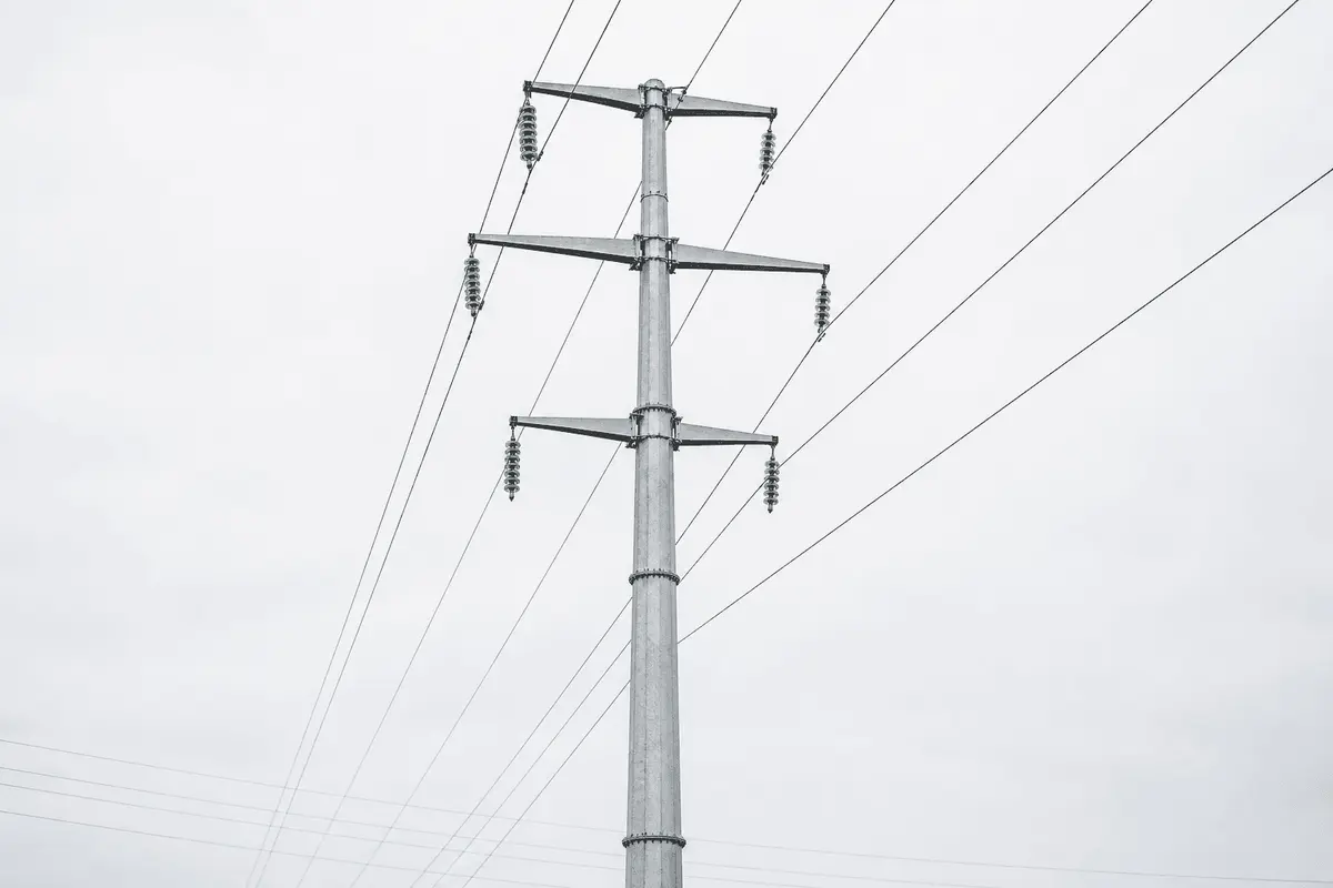
The 25m 35kV Dodecagonal Tangent Tower Flanged is a 25 m steel distribution pole for 35 kV sub-transmission lines, 1 circuit, 1 conductor per phase, and a typical 150 m straight-line span. It uses a dodecagonal steel shaft, flanged section joints, hot-dip galvanizing, suspension I-string insulators, and an EPC turnkey price range of USD 10,000-15,000 per installed tower.
Designed for distribution and sub-transmission feeders, this tangent tower supports vertical conductor weight and transverse wind load in line sections where the deflection angle is normally below 2 degrees. In a typical 35 kV overhead network, tangent or suspension structures often represent 70-80% of all towers, making unit cost, corrosion life, installation speed, and repeatable foundation detailing more important than decorative steel weight.
Product Definition and Network Role
A tangent tower is the lowest-load structure type on a 35 kV line because it carries conductors in a straight alignment instead of resisting large longitudinal angle loads. This 25 m flanged dodecagonal pole is intended for 150 m nominal spans, 1 circuit, and 3 phase conductors, with optional OPGW or shield-wire integration where lightning density exceeds 4 flashes per km² per year.
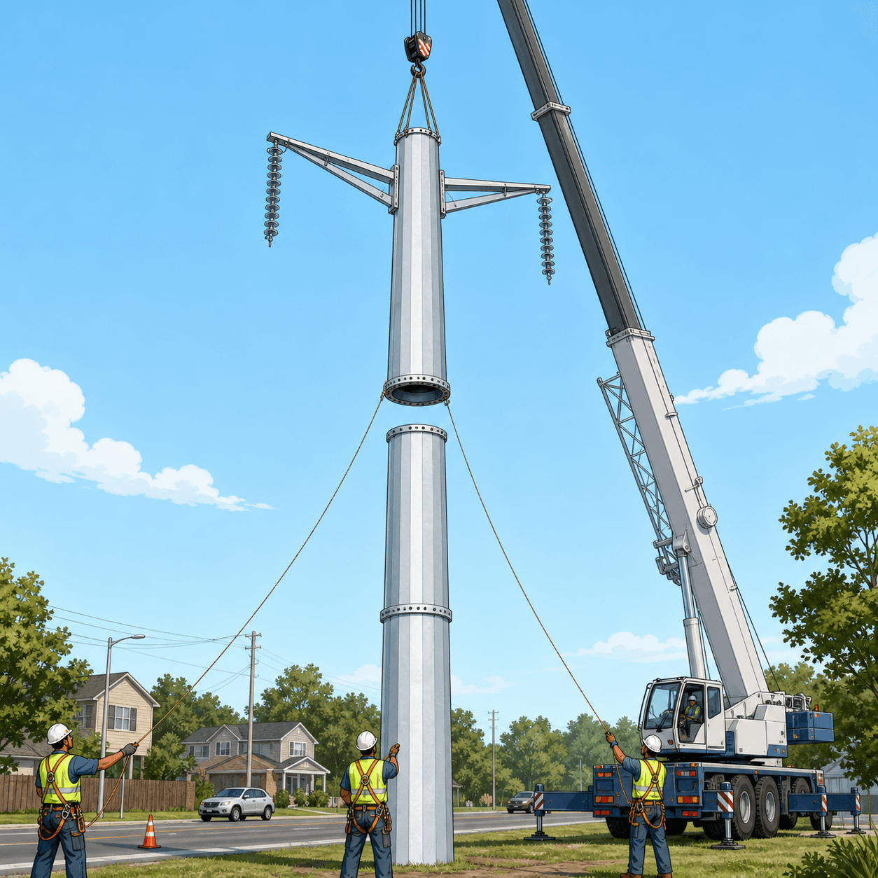
For procurement teams comparing 35 kV distribution structures, the main decision is usually between lattice angle steel, round tubular poles, prestressed concrete poles, and dodecagonal steel poles. A flanged dodecagonal pole can reduce site erection time by 30-50% compared with a bolted lattice tower of similar 25 m height because the shaft sections are factory-welded, transported in 2-3 major segments, and joined by high-strength flange bolts at site.
The configuration is optimized for rural feeders, solar plant collector lines, industrial park supply loops, and substation-to-distribution interconnections. For a 10 km line using 150 m average spans, a developer may require about 67 tangent towers before adding angle, terminal, and dead-end structures, so small savings of USD 300 per structure can affect the line budget by more than USD 20,000.
Technical Specifications
| Parameter | Value |
|---|---|
| Tower height | 25 m |
| Voltage rating | 35 kV |
| Tower type | Tangent / suspension |
| Shaft geometry | Dodecagonal steel pole |
| Connection type | Flanged section joint |
| Number of circuits | 1 circuit |
| Conductors per phase | 1 conductor |
| Typical conductor | ACSR-240 basis or project equivalent |
| Design span | 150 m |
| Wind / ice load | Class B / 15 mm ice |
| Foundation | Reinforced concrete pad or drilled pier |
| Design life | 50 years with inspection and maintenance |
| Standards basis | IEC 60826 / GB 50545 / ASCE 10-15 / IEEE 738 |
The dodecagonal shaft uses 12 flat faces to improve bending stiffness, welding access, and galvanizing drainage compared with a fully round section. For 35 kV feeders, this geometry provides a compact visual profile while maintaining sufficient section modulus for transverse wind on 3 conductors across a 150 m span and vertical load from suspension hardware.
The flanged connection allows predictable bolt pre-tension, repeatable alignment, and faster lifting than slip-joint poles when tolerances are tightly controlled. A typical 25 m pole may use 2 or 3 shaft sections, 1 base flange, 1-2 intermediate flanges, and anchor bolts sized by geotechnical design after confirming soil bearing capacity, uplift resistance, and local wind class.
System Architecture
A complete 35 kV tangent pole assembly includes the galvanized steel shaft, crossarm or bracket system, suspension insulator strings, conductor clamps, grounding downlead, climbing or maintenance provisions where required, and foundation anchor set. For 1 circuit, 3 phase positions are arranged to maintain electrical clearances under conductor swing, 15 mm radial ice, and wind load combinations defined during line profiling.
Electrical clearances are coordinated with insulation level, conductor sag, ambient temperature, and terrain conditions. IEEE 738 is commonly used to evaluate conductor thermal rating, while IEC 60826 provides internationally recognized overhead line loading principles for wind, ice, combined loading, and reliability-based design categories.
Grounding is specified to keep tower footing resistance below 10 ohms for standard distribution conditions and below 4 ohms in high-lightning corridors. Where OPGW is installed, the same structure can support lightning shielding and fiber communication, reducing the need for separate telecom poles across a 10 km corridor.
The recommended conductor basis is ACSR-240 or an equivalent aluminum conductor steel reinforced design selected by ampacity, sag, tensile limit, and local utility practice. For a 150 m span, conductor creep, final sag at maximum operating temperature, and the broken-wire condition should be checked before tower release for manufacturing.
Standards, Engineering Basis, and Compliance
SOLARTODO engineers align tower loading with IEC 60826 for overhead transmission line design criteria, GB 50545 for Chinese overhead line design practice, and ASCE 10-15 where lattice or steel structural checks are required by project owners. These standards do not replace local code approval, but they provide a defensible framework for 50-year structural service.
Conductor rating and emergency temperature review should reference IEEE 738, which is widely used for calculating current-temperature behavior of overhead conductors under wind, solar radiation, ambient temperature, and emissivity assumptions. For solar farm export lines, using IEEE 738 can prevent under-sizing a 35 kV feeder that must carry peak inverter output for 4-6 high-irradiance hours per day.
Industry planning data also supports investment in resilient grid assets. The IEA has reported that global electricity grid investment must rise materially during the 2020s to integrate renewable generation, while IRENA analysis links transmission expansion with higher renewable penetration and lower curtailment. For project developers, each 35 kV structure becomes part of an enabling grid asset rather than a stand-alone steel item.
For solar and storage interconnection, NREL has documented that collector-system design, grid interconnection, and balance-of-system costs can materially affect renewable project economics. In practice, a 25 m 35 kV pole line can connect a 10-50 MW solar plant to a substation while keeping the feeder voltage high enough to reduce I²R losses compared with lower-voltage 10 kV distribution alternatives.
Applications
A typical application is a solar farm operator in the MENA region deploying a 35 kV, 12 km collector and export line between a 30 MWac PV plant and a utility substation. With 150 m spans, the route used about 80 tangent structures, 8 angle structures, and 2 terminal structures, and the flanged poles shortened crane time by about 1 working day per 15-20 structures compared with lattice tower assembly.
Other applications include industrial park feeders, mining camp supply lines, rural electrification corridors, battery energy storage interconnections, and substation tie-lines. For a 150 m span class, the 25 m tower height gives practical clearance for rolling terrain, farm access roads, and moderate vegetation management while avoiding the heavier steel tonnage associated with 30 m or 35 m structures.
Compared with conventional reinforced concrete poles, a galvanized dodecagonal steel pole offers higher strength-to-weight ratio, easier flange repair, and more predictable dimensional quality. In many 35 kV projects, transport weight can be reduced by 20-35% versus equivalent concrete pole solutions, while breakage risk during long-haul transport is also reduced because steel sections tolerate handling better than brittle concrete members.
EPC Investment Analysis and Pricing Structure
The EPC turnkey package includes 5 work scopes: engineering, procurement, construction, commissioning, and 1-year warranty support. Engineering covers route-specific loading checks, foundation drawings, bill of materials, galvanizing inspection plan, and installation method statement; procurement covers steel fabrication, insulators, bolts, grounding, anchor cage, and export packing.
| Pricing tier | Scope | Unit price range, USD |
|---|---|---|
| FOB Supply | Equipment only, ex-works China | 6,200-10,200 |
| CIF Delivered | Equipment plus ocean freight and insurance | 7,929-13,044 |
| EPC Turnkey | Installed, commissioned, and covered by 1-year warranty | 10,000-15,000 |
| Order volume | Discount from standard supply price |
|---|---|
| 50+ towers | 5% |
| 100+ towers | 10% |
| 250+ towers | 15% |
A practical EPC estimate for 1 installed tower is USD 13,420, including a USD 7,500 galvanized steel pole assembly, USD 450 insulator and hardware set, USD 500 grounding system, USD 1,400 concrete foundation, USD 1,500 installation and commissioning, USD 1,300 engineering and QC, USD 500 logistics handling, and USD 270 warranty support. This installed budget remains inside the published USD 10,000-15,000 EPC range.
ROI for a 35 kV steel tangent pole is measured through reduced outage risk, faster build schedule, lower maintenance access cost, and avoided rebuild cost. Compared with a lower-cost timber or light concrete alternative requiring replacement or major repair after 20-30 years, a 50-year galvanized steel design can defer 1 full replacement cycle and save about USD 4,000-7,000 per structure in discounted future work.
On a 10 km feeder with 67 tangent towers, selecting flanged steel poles can reduce assembly labor by roughly 25-40% versus field-bolted lattice structures, depending on crew skill and access roads. If crane and crew costs average USD 1,200 per day, saving 8-12 site days can produce USD 9,600-14,400 in direct schedule savings before considering earlier energization of a solar or industrial load.
Payment terms are 30% T/T advance and 70% against bill of lading, or 100% irrevocable L/C at sight for qualified buyers. Project financing support can be discussed for EPC packages above USD 1,000,000, and buyers can contact [email protected] for line schedules, loading criteria, foundation data, and delivery planning.
Procurement, Manufacturing, and Quality Control
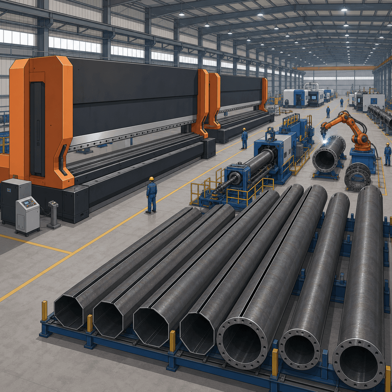
Manufacturing starts with steel plate selection, CNC cutting, press braking into 12-sided sections, longitudinal submerged-arc or CO₂ welding, flange welding, trial fitting, and hot-dip galvanizing. Dimensional checks should verify shaft straightness, flange flatness, bolt-hole tolerance, coating thickness, and match-marking before export packing into 20 ft or 40 ft containers.
Hot-dip galvanizing is specified to provide long corrosion resistance in rural, desert, and industrial atmospheres. For a 50-year design life, the inspection plan should define coating thickness measurement points, zinc repair limits, handling protection, and storage separation because 1 damaged flange face can delay installation of an entire 25 m structure.
Factory acceptance testing normally includes material certificates, weld inspection records, galvanizing reports, bolt certificates, and packing lists. For projects above 100 towers, SOLARTODO recommends 1 pre-shipment inspection batch for every 25-50 structures, with photographic traceability linked to tower marks, foundation marks, and route structure numbers.
Installation and Commissioning
Installation begins with survey staking, foundation excavation or drilling, anchor cage placement, concrete pouring, curing, pole lifting, flange bolting, hardware installation, conductor stringing, sagging, grounding, and final acceptance. For normal access conditions, 1 trained crew with 1 crane can erect multiple 25 m flanged poles per day after foundations have reached the specified concrete strength.
Commissioning checks include verticality, bolt torque, grounding resistance, insulator orientation, conductor clamp security, phase clearance, jumper clearance, anti-climbing details where specified, and as-built coordinates. Before energization at 35 kV, the owner should confirm that final sag, electrical clearance, and grounding measurements match the approved design drawings.
Maintenance typically includes a 12-month inspection after commissioning and periodic inspections every 3-5 years, depending on climate, pollution class, and utility practice. Key items include corrosion at ground level, missing bolts, damaged galvanizing, cracked insulators, loose clamps, abnormal conductor wear, and footing resistance drift after wet-dry seasonal cycles.
Digital Procurement and Related Resources
B2B buyers can View all Power Transmission Tower/Pole products to compare tangent, angle, dead-end, terminal, and monopole configurations across 10 kV to 220 kV classes. For a fast project budget, teams can Configure your system online with height, voltage, span, wind, ice, and foundation assumptions.
For technical background, procurement engineers can Learn about topic for overhead line structure selection, grounding, and conductor choices, or Learn about topic for solar farm grid connection planning. To validate a 35 kV route, conductor schedule, and EPC boundary, buyers can Request a custom quotation with route length, soil data, wind speed, ice thickness, and delivery port.
Buyer Notes
This 25 m 35 kV dodecagonal tangent tower is best suited for straight distribution line sections where the route has limited angle loading and moderate span length. If the line includes a river crossing, steep terrain, terminal gantry, or angle above 15 degrees, the structure should be changed to an angle, strain, or dead-end tower with higher longitudinal capacity.
The final price depends on steel weight, foundation type, coating requirement, conductor model, insulator selection, freight lane, site access, soil report, and local labor productivity. As a planning rule, FOB supply is typically 62-68% of installed EPC cost, while construction, engineering, logistics, commissioning, and warranty make up the remaining 32-38% on ordinary 35 kV distribution routes.
Technical Specifications
| Tower Height | 25m |
| Voltage Rating | 35kV |
| Tower Type | Tangent / suspension |
| Material | Galvanized steel dodecagonal shaft |
| Number of Circuits | 1circuit |
| Conductor Bundle | 1 x ACSR-240 basis or equivalent |
| Design Span | 150m |
| Wind/Ice Load | Class B / 15mm ice |
| Foundation | Reinforced concrete pad or drilled pier |
| Connection Type | Flanged |
| Design Life | 50years |
| Standards | IEC 60826 / GB 50545 / IEEE 738 / ASCE 10-15 |
Price Breakdown
| Item | Quantity | Unit Price | Subtotal |
|---|---|---|---|
| Galvanized dodecagonal flanged steel pole assembly | 1 pcs | $7,500 | $7,500 |
| 35kV suspension insulator and line hardware set | 1 pcs | $450 | $450 |
| Tower grounding system | 1 pcs | $500 | $500 |
| Reinforced concrete foundation package | 4 m3 | $350 | $1,400 |
| Installation and commissioning | 1 pcs | $1,500 | $1,500 |
| Engineering, drawings, and QC documentation | 1 pcs | $1,300 | $1,300 |
| Project logistics and site handling | 1 pcs | $500 | $500 |
| 1-year warranty and support | 1 pcs | $270 | $270 |
| Total Price Range | $10,000 - $15,000 | ||
Frequently Asked Questions
What does the EPC turnkey price include for this 25m 35kV tower?
Why use a dodecagonal steel pole instead of a lattice tower?
What span and conductor configuration are suitable for this tower?
Which standards are used for structural and electrical design?
What information is needed for a custom quotation?
Certifications & Standards


Data Sources & References
- •IEC 60826: Design criteria of overhead transmission lines
- •IEEE 738: Standard for calculating current-temperature relationship of bare overhead conductors
- •ASCE 10-15: Design of latticed steel transmission structures
- •NREL renewable grid interconnection and balance-of-system cost research
- •IEA electricity grids and renewable integration analysis
- •IRENA transmission expansion and renewable power integration reports
Interested in this solution?
Contact us for a customized quote based on your specific requirements.
Contact Us