Summary
The evidence is insufficient to determine whether the offered optics and aiming meet the spill-light limits. Valparaíso, Chile, is solely a proposed site for this evaluation. Require photometric files for the exact luminaire on each arm, model both arms together against the project boundary and intended-area criteria, and verify the selected configuration in the field. Specify revised optics or shielding if the offered configuration fails and the proposed revision can satisfy both sets of criteria. The evidence pack supplies a catalog record. A product PDF, page reference, and tested operating conditions are missing.
Key Takeaways
- Obtain a photometric file tied to the exact luminaire and optical assembly offered for each arm.
- Put the receiving boundary points, measurement planes, and intended-area requirements on a common site plan.
- Model the contribution of each arm and check the combined installation in every operating state subject to acceptance.
- Compare any change in optics, shielding, or aim against the same boundary and intended-area criteria.
- Measure the selected configuration in the field using the modeled points, sensor orientations, and operating states.
- Tie acceptance and substitutions to the reviewed files, installed settings, and signed measurement record.
Proposed problem
For the proposed Valparaíso application, the buyer needs to decide whether to retain the offered optics and aiming for the SOLARTODO classic twin-arm bronze smart streetlight or require a change. The decision depends on two checks. Light at the project boundary must stay within the applicable project limits, and the intended area must still receive the illumination required by the project. Compare both outcomes before approving a revision.
Ask the project owner to identify the controlling criteria and the party responsible for confirming their applicability to the proposed Chilean site. Mark the intended illuminated area and the boundary locations where limits apply. Document the metric, measurement plane, operating state, and acceptance rule for each area. Where the project requires vertical illuminance at a receptor, record the sensor height and direction as well as its location. Use those same definitions in the model and in the field record.
Source-backed product boundary
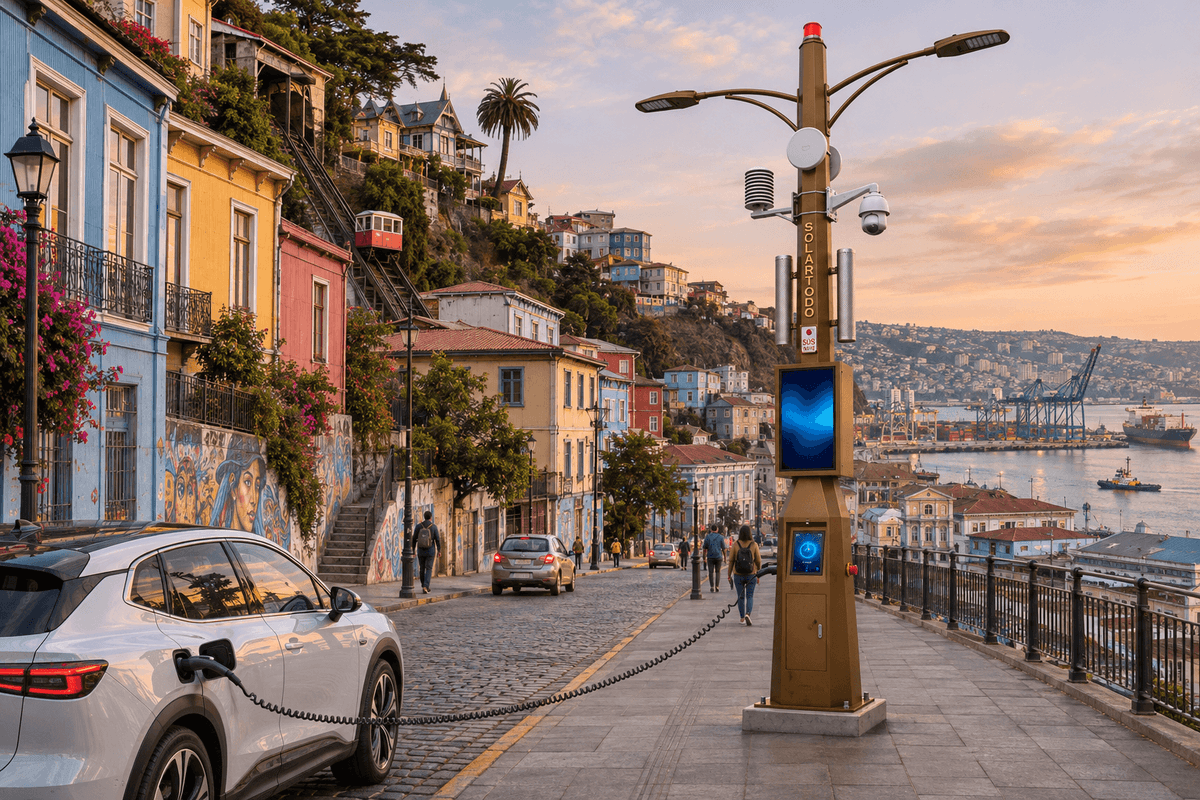
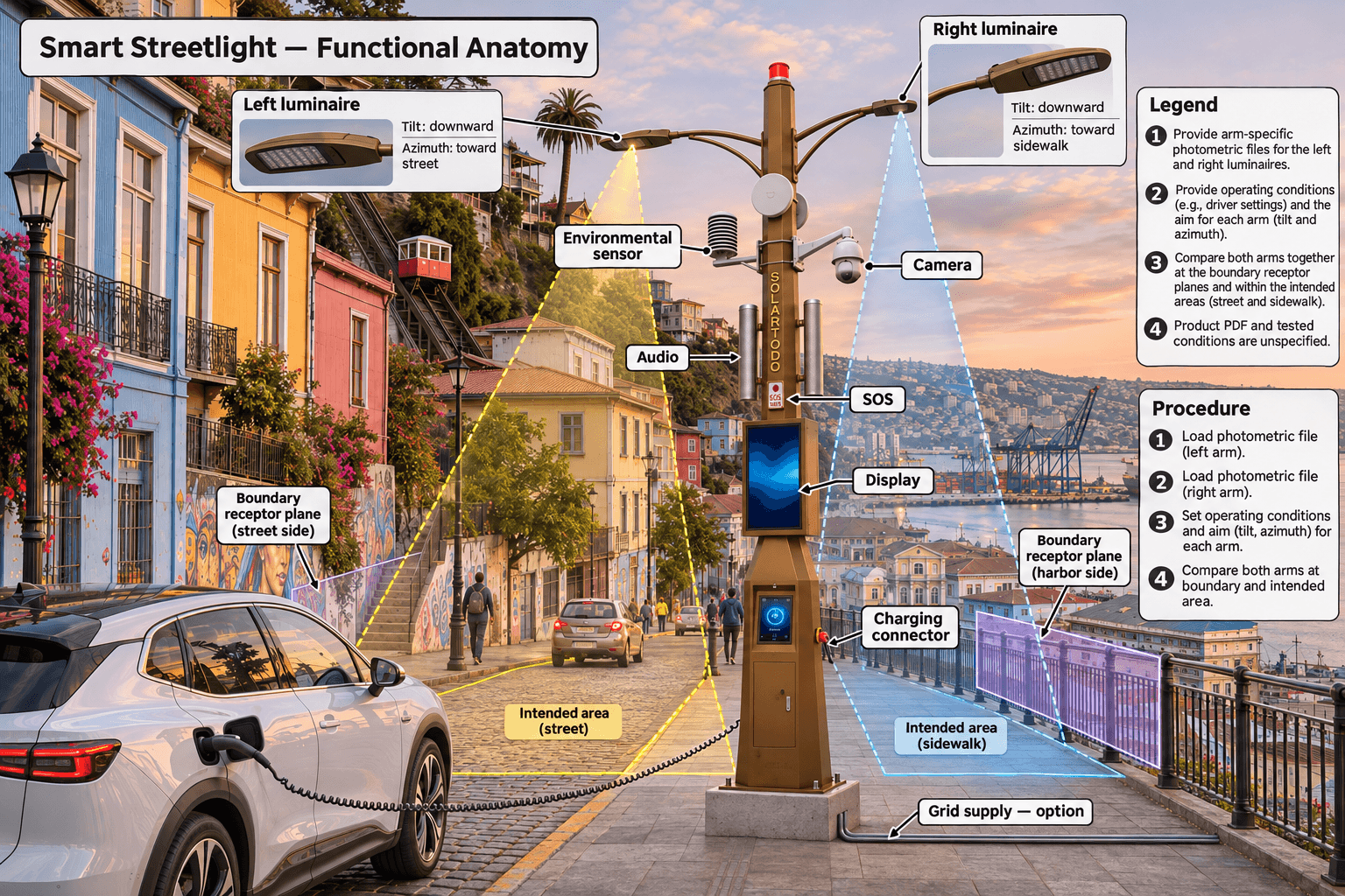
Catalog record city-catalog-2026-11-01-v1 identifies the product as the SOLARTODO classic twin-arm bronze smart streetlight. The catalog appearance shows a bronze polygonal pole with two curved luminaire arms, a PTZ camera, an environmental sensor, a display, audio/SOS, and an integrated EV charging base. Grid-fed lighting and modular communications and control are catalog options. Confirm the ordered configuration and its operating states with the supplier. SOLARTODO smart streetlight
The catalog documents the illustrated streetlight configuration and lists lighting, communications, and control options. Acceptance requires separate evidence for the luminaire and optical assembly on each arm. The evidence pack supplies neither a product PDF nor page-level photometric data and gives no mounting dimensions or tested output conditions for the offered assembly. When the supplier provides a model-specific product PDF, record its revision, page, exact model or option code, and stated test conditions. Use that PDF as the controlling product evidence wherever it conflicts with a catalog description, and ask the supplier to reconcile it with the order and photometric files.
Proposed design
Start with a surveyed drawing and an arm-by-arm schedule. For each arm, pair the exact luminaire ordering code with its optic, output setting, accessory configuration, photometric file revision, and documented test conditions. Record luminaire position, mounting height, tilt, and azimuth from the proposed installation drawing. Confirm the supplier’s photometric axes and the project’s definition of zero tilt and reference bearing. Check that each luminaire’s orientation in the model matches the aim specified in the proposed installation drawing. Obtain separate documentation for each arm, even if the supplier proposes the same luminaire on both.
Run the offered configuration first. Calculate each arm’s contribution for diagnosis and the combined contribution for acceptance. Include other proposed luminaires wherever their contribution belongs in the project calculation. Evaluate relevant receptor planes at the boundary and calculate the intended-area metrics using the same geometry and operating state. Locate the highest predicted boundary values and the locations where intended-area performance is closest to its requirement. Preserve the point coordinates and point identifiers so field readings can be compared directly.
If the offered configuration fails, compare a revised aim, a documented alternative optic, or a documented shielding arrangement. Change one variable at a time where practical so the buyer can see what each change does. For a shielded candidate, request photometry that represents the exact luminaire and shield assembly, with the installed orientation defined. Recalculate the combined installation and check the intended-area minimum, average, or uniformity wherever the project specifies those metrics.
Carry the selected candidate into a representative field trial. If the project will accept multiple operating states, give each one its own model output and test record. For any proposed control state, ask the supplier how to command and confirm the output during measurement. The U.S. Department of Energy’s connected-lighting material provides context for evaluating control behavior. DOE Connected Lighting Systems
Explicitly hypothetical measurable evaluation assumptions
The project owner should replace these trial assumptions with the approved measurement protocol and criteria before procurement acceptance.
Hypothetical evaluation assumption: The field trial records paired calculated and measured illuminance values at every designated boundary receptor in its specified plane for each state included in acceptance.
Hypothetical evaluation assumption: The intended-area survey includes the predicted minimum location and uses the project’s agreed grid and measurement plane for both the offered and revised configurations.
Hypothetical evaluation assumption: Each candidate is evaluated with both arms operating together at the documented output setting for the state under test.
Hypothetical evaluation assumption: Where switching is available and the approved protocol requires the installation’s incremental contribution, paired lights-on and lights-off readings are taken under stable background conditions.
Hypothetical evaluation assumption: Any boundary exceedance or intended-area shortfall triggers a repeat survey of the affected readings after the installed aim, optic, shield, and output state have been checked.
Survey and acceptance checklist
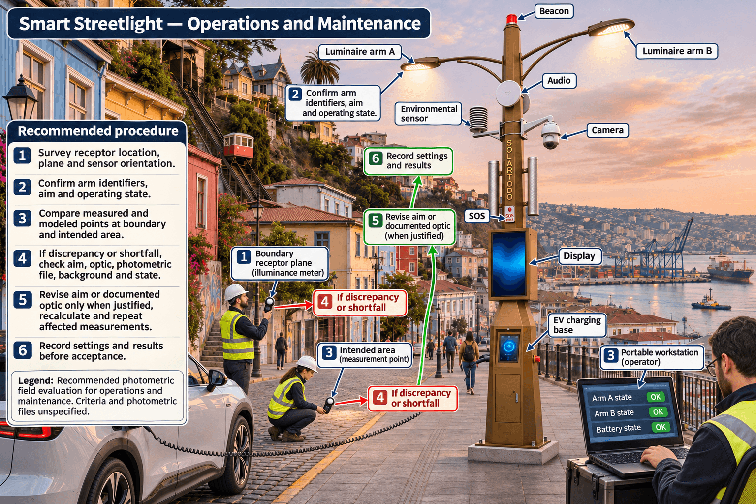
- Survey the site. Record proposed pole positions, mounting geometry, boundary alignment, ground levels, and any surveyed feature that materially affects a receiving point or the intended area. Mark receptor locations, sensor planes, and any locations where access may affect the field test.
- Review the calculation package. Confirm that each file is traceable to its arm and operating condition. Check rotations, accessory orientation, and output settings against the installation drawing. Keep point-level results, point maps, and the margin to each approved criterion.
- Inspect the installation before measuring. Check the installed luminaire and accessory identifiers, actual mounting geometry, and aim of each arm. Record the measured settings and any differences from the model. Confirm the control state and log the output setting used for each run.
- Prepare the field survey. Use an illuminance meter with current calibration. Record sensor location, height, and orientation, along with test conditions and background lighting. Follow the approved protocol for measuring total light or the installation’s contribution. Collect repeat readings where variability or proximity to a criterion could affect the decision.
- Compare results point by point. Pair each field reading with its modeled counterpart. Investigate material differences by checking geometry, photometric file matching, operating state, background light, and measurement setup. Apply the project’s agreed treatment of measurement uncertainty and retain the original readings through any retest.
- Close acceptance on both checks. Record the disposition of each boundary and intended-area criterion. If an adjustment is made in the field, record the revised configuration, update the model, and repeat the affected measurements before sign-off.
Limitations
The pack contains no exact luminaire selections, arm-specific photometric files, site survey, approved project limits, or field readings. It supports a procurement and verification method. It cannot establish that the offered assembly passes or that shielding is necessary. A catalog image provides no basis for assigning a beam distribution, mounting height, output setting, or fixed relationship between a control command and light output.
The U.S. Federal Energy Management Program publication is context for requesting traceable photometric evidence and distinguishing installation measurement from product testing. Its federal purchasing requirements and efficacy thresholds apply within the scope described by that publication and supply no acceptance criteria for the proposed Valparaíso site. DOE FEMP exterior lighting purchasing guidance
Procurement questions
- What exact luminaire, optic, output setting, and accessory configuration will be supplied for each arm, and which photometric file corresponds to each assembly?
- Which product PDF revision and page identify each proposed option, and what operating conditions apply to the reported photometry?
- How are tilt and azimuth defined, how will installers set them, and what record will verify the final orientation of each arm?
- Which revised optics or shields can the supplier document with configuration-specific photometry if the offered arrangement fails?
- Who will deliver the calculation files, conduct the field survey, and resolve a discrepancy between predicted and measured values?
- What approval and retesting will be required if an optic, shield, luminaire, mounting geometry, or output setting changes after review?
FAQ
Do the offered optics and aiming meet the proposed site’s spill-light limits?
The evidence is insufficient to determine compliance. The buyer needs the exact arm-by-arm photometry, project boundary criteria, surveyed geometry, and field measurements for the selected configuration.
Can the catalog appearance be used as photometric evidence?
The catalog identifies the streetlight by name and shows its appearance. Request documentation and photometric files tied to the exact luminaire, optic, accessories, and operating conditions for each arm.
Why calculate both arms together?
Evaluate the proposed operating configuration at the boundary receptors and throughout the intended area. Separate calculations help identify the source of a problem, while the combined calculation supports the acceptance decision.
Where should boundary measurements be taken?
Use the project’s designated receptor locations and measurement planes. Include predicted boundary peaks in the survey and record the sensor height and orientation wherever the project specifies them.
When should the specification require revised optics or shielding?
Require a documented revision if the offered configuration fails and the revision can meet the boundary and intended-area criteria. Verify the selected revision in the field.
What should be checked after changing the aim or adding a shield?
Recalculate the boundary and intended-area metrics for the revised assembly and repeat the affected field measurements. Confirm the installed orientation and operating state during the retest.
How should existing background light be handled?
Follow the approved protocol for total light or the project’s incremental contribution. Where the protocol calls for an incremental measurement and switching is available, use paired readings under stable background conditions.
Can the U.S. procurement guidance establish acceptance criteria for Valparaíso?
The U.S. guidance provides context for requesting evidence. Use the criteria confirmed for the proposed Chilean site to govern acceptance.
References
- SOLARTODO catalog record
city-catalog-2026-11-01-v1documents the appearance and listed options for the classic twin-arm bronze smart streetlight. The evidence pack omits a product PDF URL, page reference, and tested operating conditions. SOLARTODO smart streetlight catalog - U.S. Department of Energy. Connected lighting research and test-bed context. Connected Lighting Systems
- U.S. Department of Energy Federal Energy Management Program. U.S. federal purchasing context and references to photometric test methods. Purchasing Energy-Efficient Exterior Lighting
Proposed Equipment
- SOLARTODO classic twin-arm bronze smart streetlight
- Bronze polygonal pole with two curved luminaire arms
- PTZ camera
- Environmental sensor
- Display
- Audio/SOS
- Integrated EV charging base