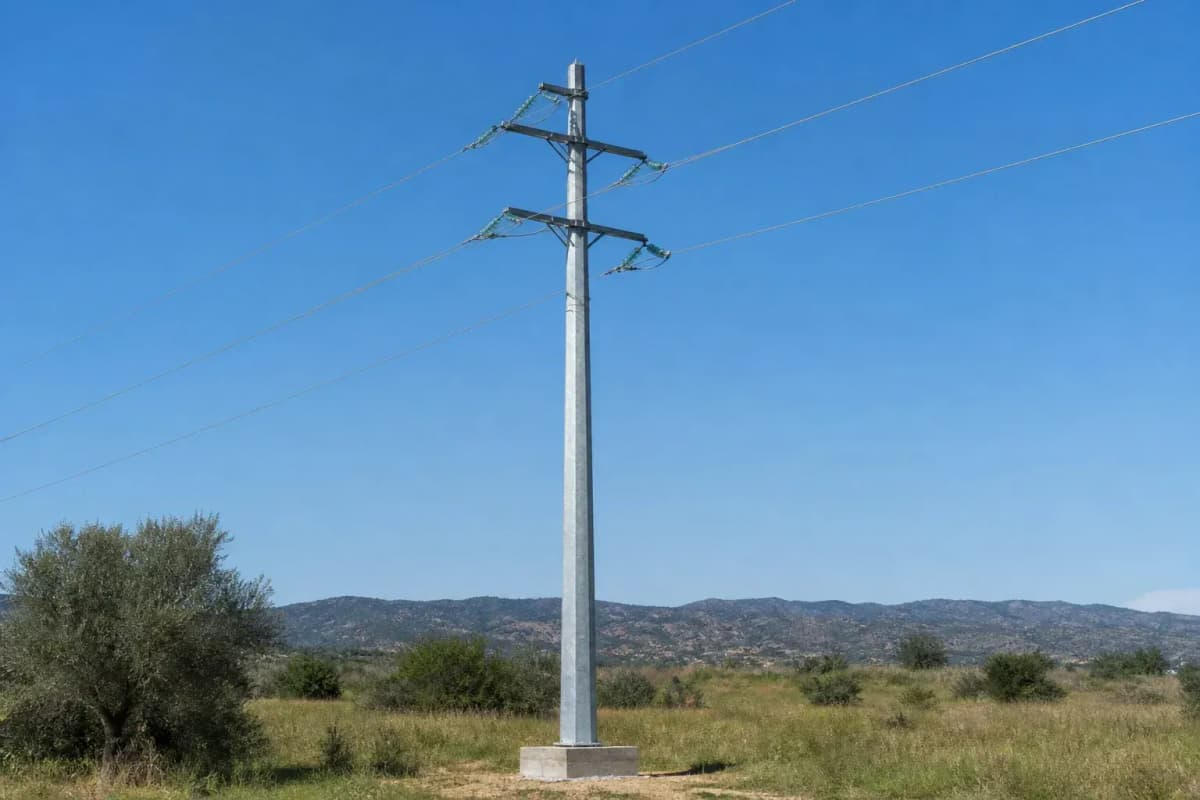
12m 10kV Octagonal Distribution Slip-Joint - Urban Steel Monopole
Key Features
- 12 m octagonal hot-dip galvanized steel monopole for 10 kV distribution feeders
- 48 m nominal design span with 1 circuit and 1 conductor per phase
- Slip-joint section design supports faster field assembly with 2 shorter pole sections
- 50-year design life target with grounding below 10 ohm, or below 4 ohm in high-lightning areas
- EPC turnkey price range of USD 3,200-5,040 including commissioning and 1-year warranty
The 12m 10kV Octagonal Distribution Slip-Joint is a hot-dip galvanized steel monopole for single-circuit urban and suburban feeders, designed for a 48 m span, Class B wind loading, and 15 mm ice. EPC turnkey pricing is USD 3,200-5,040 per installed pole including engineering, procurement, construction, commissioning, and 1-year warranty support.
Description
The 12m 10kV Octagonal Distribution Slip-Joint is a compact steel monopole for 10 kV single-circuit distribution feeders with 1 conductor per phase and a nominal 48 m design span. The 12 m, 8-sided hot-dip galvanized pole uses a slip-joint connection to simplify transport, field lifting, and section assembly for urban streets, industrial parks, solar plant feeders, and suburban distribution corridors.
This SOLARTODO product page defines a 1-pole EPC package priced at USD 3,200-5,040, with FOB supply at USD 1,984-3,427 and CIF delivered pricing at USD 2,537-4,383. The engineering basis references IEC 60826:2017 for overhead-line loading principles, IEEE 738-2023 for bare overhead conductor temperature calculations, and GB 50545 for Chinese overhead transmission-line design practice, while final values must be checked against 1 local utility code and 1 site-specific wind and soil report.
Product Definition and Use Case
The 12 m octagonal distribution slip-joint pole is specified for 10 kV distribution, 1 circuit, 1 conductor per phase, and a typical 48 m span where a low-footprint support is preferable to a 4-leg lattice tower. Compared with a conventional small lattice structure occupying roughly 4-9 m² at ground level, a single steel monopole can reduce the visible foundation footprint by about 60-75%, depending on base diameter, anchor-bolt circle, sidewalk clearance, and utility setback rules.
The pole body is fabricated from formed steel plates into an 8-sided polygon cross-section, then protected by hot-dip galvanizing for outdoor corrosion resistance over a planned 50-year design life with scheduled inspection. For procurement teams comparing alternatives, steel octagonal monopoles usually offer a stronger visual profile than FRP distribution poles at 12 m height, while remaining easier to transport than long welded tubular poles because slip-joint sections can be nested or shipped in shorter lengths.
This model fits urban and suburban feeders, solar farm internal collection roads, small industrial substations, commercial microgrid interconnection points, and distribution upgrades where 10 kV clearance and mechanical safety matter more than ultra-high-voltage tower economics. For broader portfolio comparison, buyers can View all Power Transmission Tower/Pole products or Configure your system online with height, voltage, conductor, foundation, and coating assumptions before requesting a budgetary design.
System Architecture
The standard architecture uses 1 galvanized octagonal pole, 1 slip-joint pole interface, 1 crossarm or compact bracket set, 3 phase insulator positions, and 1 grounding path bonded to the foundation rebar or dedicated earth electrode. A typical 10 kV feeder arrangement places ACSR conductors on porcelain or polymer insulators, with optional surge arresters, drop-out fuses, disconnect switches, or OPGW depending on whether the route includes 1 feeder tap, 1 communications path, or a local lightning-risk requirement.
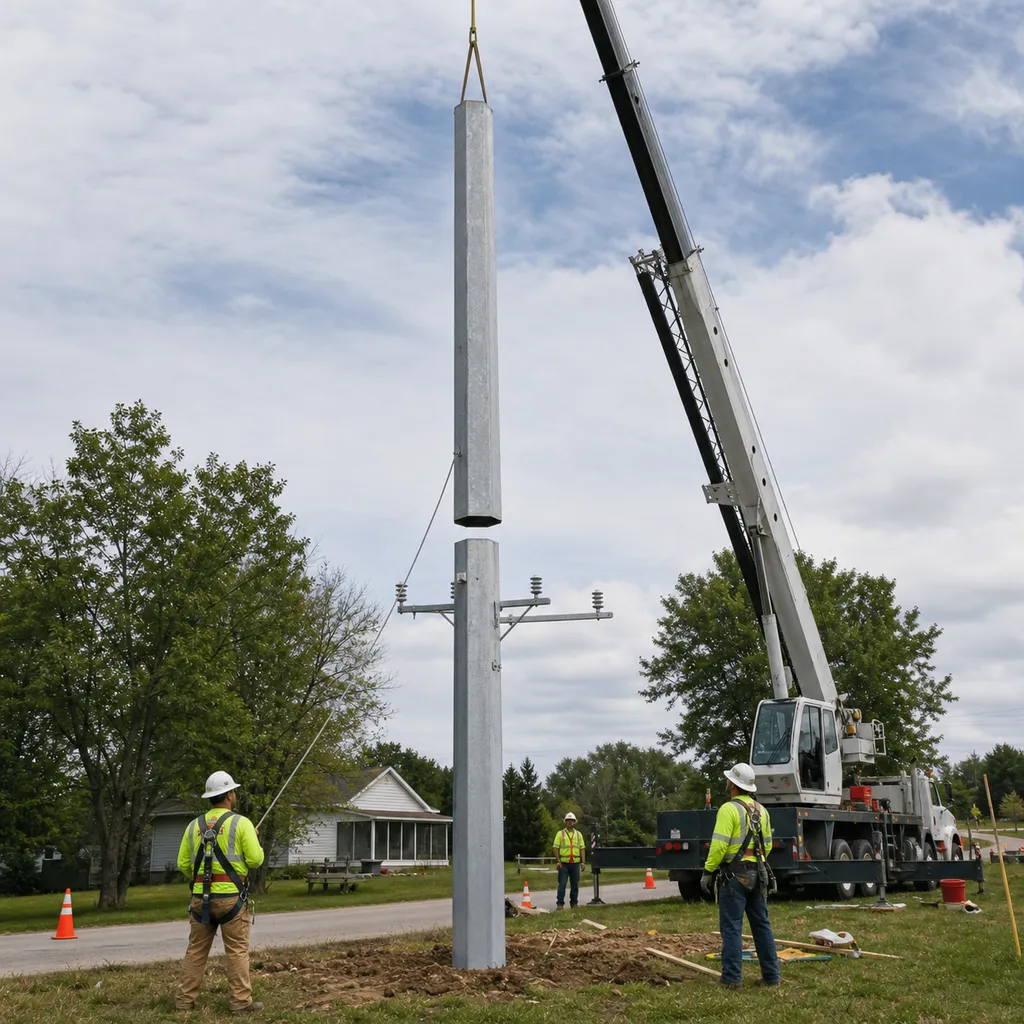
The slip-joint connection transfers bending and axial loads through controlled overlap between the upper and lower pole sections, reducing the number of large bolted flange interfaces from 2 or more to 1 primary joint in many 12 m configurations. This layout is useful where road access allows only a small crane, because a crew can stage 2 shorter steel sections instead of handling 1 full-length 12 m pole in a congested street or project road.
The foundation interface is normally supplied as a base plate with anchor bolts or as an embedded shaft configuration, selected after reviewing 1 geotechnical report, allowable bearing pressure, overturning moment, and groundwater level. For normal lightning areas the grounding target is typically below 10 ohms, while high-lightning or sensitive industrial corridors may specify below 4 ohms with additional rods, chemical grounding, or counterpoise conductors.
Technical Specifications
The baseline design envelope is 12 m height, 10 kV voltage rating, 48 m design span, Class B wind assumption, 15 mm ice, and 50-year design life with maintenance. IEC 60826:2017 specifies reliability-based loading and strength requirements for overhead lines and can be applied below 45 kV when a project owner adopts its method; see the IEC record at https://webstore.iec.ch/en/publication/33148 for the 2017 fourth edition.
| Parameter | Standard Configuration | Engineering Note |
|---|---|---|
| Nominal height | 12 m | Urban distribution class |
| Voltage class | 10 kV | Medium-voltage feeder |
| Pole geometry | 8-sided octagonal steel | Compact monopole profile |
| Circuit count | 1 circuit | Single distribution feeder |
| Conductors | 1 per phase | ACSR or project-specified equivalent |
| Design span | 48 m | Confirm with sag-tension study |
| Ice load | 15 mm | Template value requiring local validation |
| Ground resistance | less than 10 ohm | less than 4 ohm in high-lightning zones |
| Design life | 50 years | With coating inspection and maintenance |
| Connection | Slip joint | Section overlap field assembly |
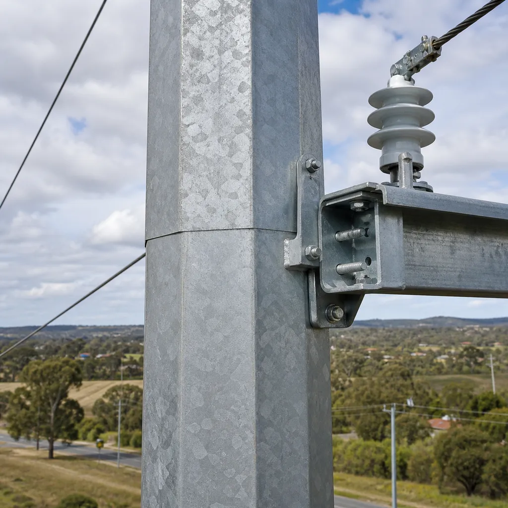
Material selection is based on hot-dip galvanized steel because a 12 m pole must resist wind pressure, conductor tension, broken-wire loading, construction loads, and corrosion exposure over decades. The galvanizing process should be documented with coating-thickness reports, visual inspection, and repair procedures consistent with project requirements such as ISO 1461 or ASTM A123 where the contract selects 1 international zinc-coating benchmark.
Conductor selection should be confirmed through a sag-tension and ampacity calculation rather than by pole height alone, because 10 kV distribution circuits may use different ACSR sizes depending on current, ambient temperature, solar heating, and allowable conductor temperature. IEEE 738-2023 provides the calculation method for the current-temperature relationship of bare overhead conductors; the IEEE page at https://standards.ieee.org/ieee/738/10207/ identifies the 2023 active standard.
Engineering Standards and Design Basis
A responsible design package should combine at least 5 document classes: general arrangement drawings, structural calculations, foundation drawings, material certificates, and inspection/test plans. IEC 60826 supports probabilistic or semi-probabilistic loading concepts, GB 50545 supports Chinese overhead-line design practice, IEEE 738 supports conductor thermal rating, and ASCE 10-15 provides steel lattice transmission-structure guidance that is often referenced for structural methodology comparisons even when the final product is a monopole.
The design must also consider clearances, public safety, earthing, route survey constraints, conductor blowout, insulator creepage, climbing prevention, anticorrosion category, and utility operating practice for 10 kV networks. NREL transmission planning research emphasizes the role of transmission and grid infrastructure in maintaining reliability and affordability as systems integrate more renewable resources; see https://www.nrel.gov/grid/transmission-planning.html for its transmission planning program and 2024 grid-modernization references.
For renewable and electrification-driven grid expansion, the International Energy Agency notes that power grids have served electricity systems for more than 100 years and now require significant upgrades for electric vehicles, heat pumps, and renewable generation growth; see IEA, Electricity Grids and Secure Energy Transitions, https://www.iea.org/reports/electricity-grids-and-secure-energy-transitions. For a 12 m 10 kV pole, that macro trend translates into practical demand for shorter installation windows, modular structures, and repeatable feeder construction packages.
IRENA also links resilient power infrastructure and quality infrastructure to renewable integration, mini-grid reliability, and investment confidence, including its 2020 smart mini-grid quality-infrastructure report at https://www.irena.org/publications/2020/Dec/Quality-infrastructure-for-smart-mini-grids. For SOLARTODO buyers, this means procurement should ask for 1 traceable bill of materials, 1 coating inspection record, 1 drawing revision table, and 1 commissioning checklist for every batch of poles.
Manufacturing and Quality Control
Manufacturing starts with steel plate procurement, CNC cutting, bending into 8 flat faces, longitudinal welding, trial fitting, drilling, galvanizing, and packaging. A practical inspection plan includes dimensional checks at 3 locations along each section, weld visual inspection over 100% of accessible seams, zinc coating measurement at multiple points, and verification that slip-joint overlap marks are legible before shipping.
Quality records should include mill test certificates, welding consumable records, galvanizing certificates, factory inspection photographs, packing lists, and bolt/nut washer specifications for 1 complete pole assembly. For export projects, packaging should protect galvanized surfaces during 30-60 days of ocean freight, with separator pads, lifting marks, bundle labels, and corrosion-safe wrapping around threaded anchor bolt components.
Applications
This 12 m 10 kV slip-joint pole is commonly used for distribution feeders serving 1-5 MW solar farms, industrial estate ring mains, rural-to-urban transition roads, logistics parks, water-pumping stations, and compact utility corridors. The 48 m span basis allows planners to estimate about 20.8 poles per kilometer before angle poles, terminal poles, transformer structures, road crossings, and special foundations are added.
For a representative MENA solar farm scenario, assume an internal 10 kV feeder serving a 3 MW PV block with 18 poles, sandy soil requiring enlarged concrete foundations, a 45 degrees Celsius summer design check, and a 1.2 km road-aligned route. Under this scenario, EPC cost at USD 3,200-5,040 per pole gives a pole-line structural budget of about USD 57,600-90,720 before switchgear, transformer stations, protection relays, and utility interconnection fees.
Related engineering guides are available through SOLARTODO knowledge resources, including Learn about topic for feeder design concepts and Learn about topic for grounding, lightning, and smart infrastructure integration. Buyers who need route-specific line spotting, quantity takeoff, or foundation sizing can Request a custom quotation with 1 route map, 1 soil report, 1 conductor selection, and 1 local wind-speed requirement.
Cloud Monitoring
The pole is a passive structure, but it can support smart-grid accessories such as 1 fault passage indicator, 1 pole-mounted RTU, 1 distribution sensor, or 1 low-power camera when the project requires feeder visibility. A cloud monitoring package normally adds a sensor cabinet, communications module, surge protection, power supply, and dashboard integration, while the structural design must confirm extra bracket loads and cable routing at 12 m height.
Cloud-based line monitoring is most useful when a feeder has 10 or more poles, difficult truck access, or a high cost of outage response. Data points may include phase current, line temperature estimate, fault passage direction, pole tilt, cabinet door state, and weather inputs, but these functions are optional and should be priced separately from the base USD 3,200-5,040 EPC turnkey pole package.
EPC Investment Analysis and Pricing Structure
EPC turnkey delivery includes 5 work scopes: engineering, procurement, construction, commissioning, and 1-year warranty support. For this 12 m 10 kV pole, engineering covers drawings and calculations, procurement covers steel pole fabrication and accessories, construction covers foundation and erection, commissioning covers inspection and grounding checks, and warranty covers documented defects within 12 months after handover.
| Pricing tier | Scope | Unit price range, USD |
|---|---|---|
| FOB Supply | Equipment only, ex-works China | 1,984-3,427 |
| CIF Delivered | Equipment plus ocean freight and insurance | 2,537-4,383 |
| EPC Turnkey | Installed, commissioned, and 1-year warranty | 3,200-5,040 |
| Order volume | Discount from applicable tier | Commercial note |
|---|---|---|
| 50+ poles | 5% | Batch drawings and shared inspection plan |
| 100+ poles | 10% | Optimized packaging and repeated foundation type |
| 250+ poles | 15% | Project procurement schedule and container planning |
ROI should be evaluated as avoided civil works, shorter outage windows, lower land-take, and reduced maintenance access cost rather than as direct energy generation revenue. In a 100-pole feeder using compact monopoles, a conservative comparison against small lattice supports can reduce occupied foundation area by 60-75% and save 1-2 installation days per 10 structures where crane access and prefabricated foundations are available.
For a budget example, replacing a conventional option that requires larger foundations, extra steel members, and longer assembly time can save about USD 250-700 per pole in civil works and installation logistics, depending on soil and labor rates. At a 100-pole order, that equals USD 25,000-70,000 in potential project-level savings, producing a simple payback within 1 construction cycle when right-of-way, traffic control, and installation delays are included.
Standard payment terms are 30% T/T advance plus 70% against B/L copy, or 100% irrevocable L/C at sight for approved bank instruments. Project financing review is available for qualified EPC packages above USD 1,000,000, and commercial inquiries should be sent to [email protected] with pole quantity, delivery port, project country, foundation preference, and required Incoterms.
Procurement Notes
A complete RFQ should include at least 10 inputs: project country, route length, quantity, wind speed, ice thickness, conductor type, insulator type, foundation type, delivery port, and required documentation language. Without these values, SOLARTODO can provide only the standard 12 m, 10 kV, 48 m span budgetary configuration, not a final construction-ready calculation package.
Buyers should also identify whether the pole will carry only 3 phase conductors or also accessories such as a neutral, OPGW, streetlight arm, transformer, switch, metering cabinet, camera, antenna, or surge arrester set. Every extra attachment changes wind area, eccentric moment, corrosion interfaces, and maintenance access, so it should appear as 1 priced line item in the technical and commercial schedule.
Lifecycle and Maintenance
A 50-year service target requires planned maintenance, not a no-inspection assumption. A practical program checks coating damage after transport, bolt torque after installation, grounding resistance at commissioning, visual corrosion every 12 months in aggressive environments, and post-storm inspection after wind or ice events above the project threshold.
The main maintainability advantage of a monopole is reduced member count: an octagonal steel shaft has fewer exposed bolted members than a lattice tower with dozens of angles and gusset plates. In medium-voltage distribution, this can reduce routine visual inspection points by more than 50% compared with small lattice alternatives, while still requiring careful checks at the base plate, slip-joint overlap, grounding connection, insulator hardware, and conductor attachment points.
Ordering Workflow
SOLARTODO recommends a 4-step ordering workflow: submit the RFQ package, receive a budgetary design and price, confirm local code and foundation assumptions, then approve production drawings. For a normal export order, the commercial schedule should allow 2-3 weeks for drawing confirmation, 3-6 weeks for fabrication and galvanizing, and 4-8 weeks for ocean logistics depending on port, quantity, and inspection hold points.
For projects that combine solar, energy storage, smart lighting, security, telecom, and power towers, SOLARTODO can align the 10 kV pole package with adjacent infrastructure scopes in 1 coordinated procurement file. This reduces mismatched brackets, inconsistent coatings, duplicated grounding kits, and unclear warranty boundaries across multiple suppliers on the same site.
Technical Specifications
| Tower Height | 12m |
| Voltage Rating | 10kV |
| Tower Type | distribution |
| Material | steel_octagonal |
| Number of Circuits | 1circuits |
| Conductor Bundle | 1xACSR |
| Design Span | 48m |
| Wind/Ice Load | Class B / 15mm ice |
| Foundation | Concrete foundation or site-specific pile foundation |
| Connection Type | slip_joint |
| Design Life | 50years |
| Standards | IEC 60826 / GB 50545 / IEEE 738 |
Price Breakdown
| Item | Quantity | Unit Price | Subtotal |
|---|---|---|---|
| Hot-dip galvanized octagonal steel pole | 1 pcs | $2,100 | $2,100 |
| Slip-joint crossarm and hardware set | 1 pcs | $420 | $420 |
| Composite 10 kV insulator set | 3 pcs | $95 | $285 |
| ACSR conductor connection and clamp allowance | 1 pcs | $225 | $225 |
| Grounding kit and earthing accessories | 1 pcs | $350 | $350 |
| Concrete foundation materials allowance | 1 pcs | $520 | $520 |
| Engineering drawings and QC documentation | 1 pcs | $280 | $280 |
| Installation and commissioning | 1 pcs | $450 | $450 |
| 1-Year warranty and support | 1 pcs | $210 | $210 |
| Total Price Range | $3,200 - $5,040 | ||
Frequently Asked Questions
What is included in the EPC turnkey price for the 12m 10kV pole?
Can this 12 m octagonal pole be used for both urban and solar farm distribution?
Why use a slip-joint instead of a fully welded 12 m pole?
Which standards apply to the technical design?
What information is needed for a final quotation?
Certifications & Standards



Data Sources & References
- •IEC 60826:2017 Design criteria of overhead transmission lines, https://webstore.iec.ch/en/publication/33148
- •IEEE 738-2023 Standard for Calculating the Current-Temperature Relationship of Bare Overhead Conductors, https://standards.ieee.org/ieee/738/10207/
- •IEA Electricity Grids and Secure Energy Transitions, 2023, https://www.iea.org/reports/electricity-grids-and-secure-energy-transitions
- •NREL Transmission Planning and Grid Modernization research, https://www.nrel.gov/grid/transmission-planning.html
- •IRENA Quality Infrastructure for Smart Mini-grids, 2020, https://www.irena.org/publications/2020/Dec/Quality-infrastructure-for-smart-mini-grids
- •IRENA Renewable Capacity Statistics 2026 publication index, https://www.irena.org/publications
Interested in this solution?
Contact us for a customized quote based on your specific requirements.
Contact Us