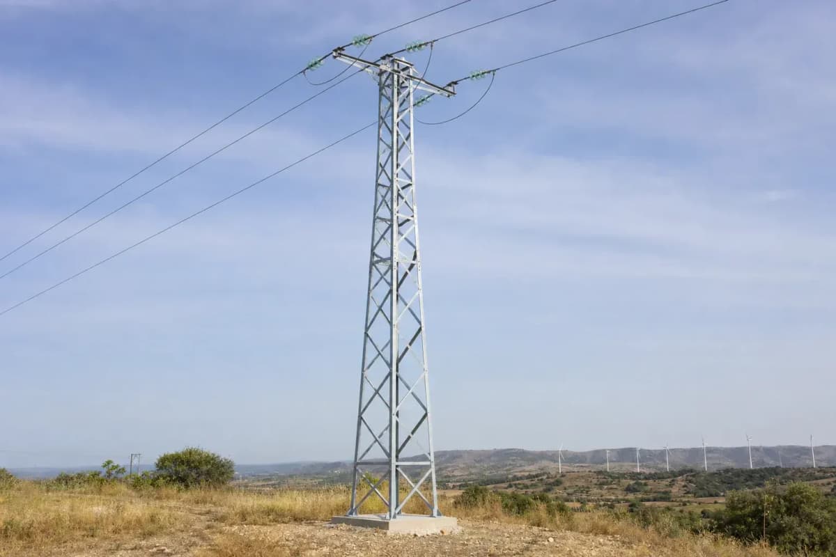
18m 35kV Lattice Distribution Slip-Joint - Single-Circuit Steel Tower
Key Features
- 18 m galvanized steel lattice tower for 35 kV single-circuit distribution feeders
- 108 m design span reduces structure count by about 25.6% versus an 80 m span layout over 10 km
- Class B wind and 15 mm ice design basis with IEC 60826 and ASCE/SEI 10-15 references
- Grounding target below 10 ohm standard or below 4 ohm in high-lightning areas
- EPC turnkey price range from $7,200 to $10,800 per installed tower position
The 18m 35kV Lattice Distribution Slip-Joint is a single-circuit galvanized steel lattice tower for 35 kV distribution and sub-transmission feeders, using 1 conductor per phase, a 108 m design span, Class B wind loading, and 15 mm ice design assumptions. SOLARTODO supplies FOB, CIF, and EPC turnkey packages from $4,464 to $10,800 per tower position.
Description
The 18m 35kV Lattice Distribution Slip-Joint is a single-circuit steel lattice tower for 35 kV distribution and sub-transmission feeders, specified at 18 m height, 108 m design span, 1 conductor per phase, and a 50-year structural design life. It is engineered for medium-span utility interconnection, solar farm evacuation, rural feeder reinforcement, and smart-infrastructure corridors where 1 tower position must combine mechanical reliability, grounding continuity, and predictable EPC cost control.
SOLARTODO positions this 18 m structure within the View all Power Transmission Tower/Pole products portfolio for B2B buyers that need 35 kV overhead distribution assets between substations, PV collection networks, battery energy storage plants, industrial loads, and telecom-backed monitoring nodes. The design basis follows IEC 60826:2017 for overhead-line loading and strength concepts, ASCE/SEI 10-15 for latticed steel transmission structures, IEEE 738-2023 for conductor current-temperature calculation, and GB 50545 for Chinese overhead transmission-line design practice.
Technical Specifications
| Parameter | 18m 35kV Lattice Distribution Slip-Joint Value |
|---|---|
| Nominal tower height | 18 m |
| Voltage class | 35 kV AC |
| Line function | Distribution / sub-transmission |
| Circuit configuration | 1 circuit |
| Conductors per phase | 1 ACSR conductor |
| Design span | 108 m |
| Connection type | Slip-joint modular steel assembly |
| Material | Q420 galvanized angle steel, optional Q460 tubular members |
| Wind / ice basis | Class B wind, 15 mm ice |
| Grounding target | <10 ohm standard, <4 ohm high-lightning areas |
| Design life | 50 years with inspection and maintenance |
| EPC price range | $7,200-$10,800 per installed tower position |
The 18 m height gives a practical clearance envelope for 35 kV feeders using 1 ACSR conductor per phase, with a 108 m planning span that balances conductor sag, pole count, right-of-way cost, and foundation volume. For procurement comparison, a 10 km feeder at 108 m average span requires about 93 structures, while the same line at 80 m average span requires about 125 structures, a 25.6% increase in structure count before bends, terminals, and angle towers are added.
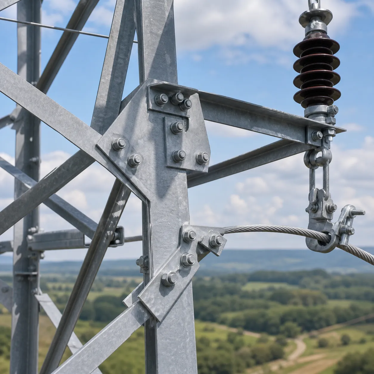
The lattice body uses hot-dip galvanized Q420 angle steel for the base specification, with Q460 tubular or hybrid members available where wind exposure, transport limits, or aesthetics require a stronger section. A 3.2 ton representative steel package at $1,400 per ton accounts for about $4,480 of the EPC bill of materials, while galvanizing is specified to support a 50-year service target under normal utility inspection cycles.
System Architecture
The tower architecture is a 4-leg steel lattice structure with bolted crossarms, 1 single 35 kV circuit, 3 phase positions, 1 conductor per phase, and provision for 1 overhead grounding or OPGW route where project communications justify the fiber cost. IEC 60826:2017 states that overhead-line loading and strength requirements can be derived from reliability-based principles for lines above 45 kV and can also be applied below 45 kV, which makes it a useful reference for 35 kV utility designs when local codes require probabilistic climate assumptions.
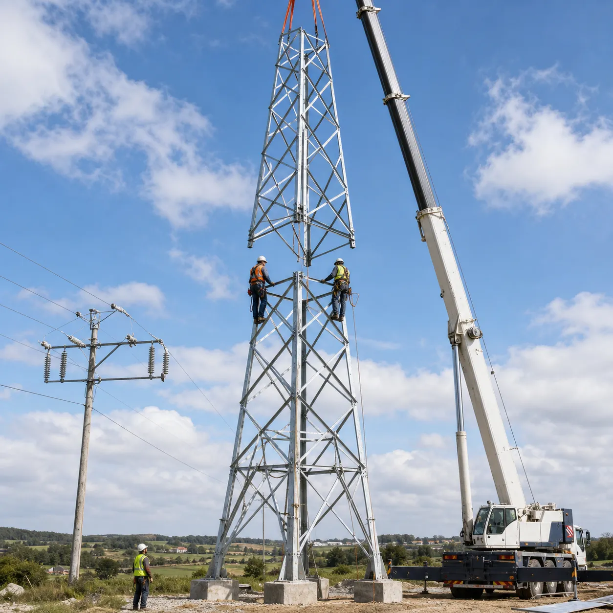
The slip-joint configuration divides the 18 m tower into transportable steel sections, reducing crane time and site handling compared with a fully welded pole section of similar height. In a representative 1-tower installation, a slip-joint lattice assembly can reduce specialized heavy-lift dependency by about 15-25% compared with a conventional single-piece tubular pole, although final savings depend on access road width, foundation elevation, and local lifting regulations.
Electrical architecture is based on ACSR conductors, porcelain or composite polymer insulators, surge-protection coordination, and a grounding system designed for less than 10 ohm tower footing resistance in normal soil. In high-lightning corridors, SOLARTODO recommends a less-than-4-ohm target, 1 OPGW or shield-wire path where applicable, and at least 2 buried radial electrodes per tower position after soil-resistivity testing.
IEEE 738-2023 provides a recognized method for calculating the current-temperature relationship of bare overhead conductors under steady or time-varying current and weather conditions. For a 35 kV feeder using 1 conductor per phase, this matters because thermal rating, sag clearance, emergency loading, and renewable export curtailment risk are all linked to conductor temperature, ambient wind speed, solar heating, and allowable operating limits.
Materials, Corrosion Protection, and Mechanical Design
The baseline steel is Q420 hot-dip galvanized angle steel, selected for a practical strength-to-cost ratio in 35 kV distribution structures. At an industry reference price of about $1,400 per galvanized ton, the lattice tower offers a transparent procurement model, while optional Q460 tubular steel at about $1,500 per ton can be used for localized reinforcement in higher wind zones or heavy conductor tension conditions.
Lattice design distributes wind and conductor loads through triangulated members, which typically provides a lower steel mass than an equivalent non-guyed monopole for the same 18 m clearance class. Compared with a conventional 18 m concrete or heavy tubular pole alternative, the lattice option can reduce transport weight by 20-35% for remote sites, while increasing the number of bolted components that must be checked during 1-year and 5-year inspections.
Foundation selection depends on 3 project variables: soil bearing capacity, groundwater depth, and overturning moment under broken-wire or maximum wind cases. A representative cast-in-place concrete foundation of 5 m³ at $350 per m³ equals $1,750, while pile foundations at $800 per meter may be justified in soft coastal soils, flood plains, or sites with low allowable bearing pressure below 100 kPa.
Insulation can be supplied as 3 porcelain strings at about $80 per unit or 3 composite polymer strings at about $150 per unit. Composite insulators weigh less, offer improved vandal resistance, and reduce installation handling risk on 18 m structures, while porcelain remains attractive where utilities have 20-30 years of maintenance history and standardized stocking programs.
Applications
This 18 m 35 kV lattice tower is suitable for solar farm evacuation lines, battery energy storage interconnection, industrial park feeders, mining distribution lines, agricultural pumping networks, telecom power corridors, and rural utility reinforcement. A typical solar-plus-storage project may use 35 kV collection feeders from 1 MW to 80 MW blocks, with 18 m structures placed at about 108 m intervals where terrain, access, and conductor sag permit.
For a representative MENA solar farm scenario, assume a 50 MWac PV plant, 3.5 km of 35 kV overhead evacuation line, 108 m average span, 33 tower positions, 15 mm ice-equivalent mechanical allowance for conservative procurement, and less-than-10-ohm grounding at every structure. At an EPC midpoint of $9,000 per tower, the tower-position budget is about $297,000 before terminal gantries, switchgear, protection relays, and substation expansion are added.
The IEA 2023 report Electricity Grids and Secure Energy Transitions identifies grid expansion and modernization as a bottleneck risk for renewable deployment, while the IEA 2025 transmission-grid analysis notes electricity demand growth near 4% annually through 2027. For B2B project developers, 35 kV distribution structures are therefore not minor accessories; they are enabling assets that can determine interconnection timing, curtailment exposure, and COD readiness.
Cloud Monitoring
The steel tower itself is passive infrastructure, but the 35 kV corridor can be integrated with OPGW, IoT weather stations, line-temperature sensors, fault passage indicators, and gateway devices for feeder monitoring. IRENA’s 2023 smart-electrification work maps 100 innovation solutions across technology, planning, operation, markets, and business models, which supports the use of digitally monitored distribution assets in renewable-heavy networks.
A monitoring-ready 18 m tower position can include 1 grounding node, 1 optional OPGW clamp set, 1 sensor mounting bracket, and 1 communications route into a utility SCADA, DERMS, or cloud dashboard. SOLARTODO can align hardware submittals with the Configure your system online workflow, allowing engineers to compare 18 m, 24 m, and 30 m structure families before issuing a bill of quantities.
NREL has highlighted that distributed energy resources affect distribution planning and operation through voltage control, bidirectional power flows, protection coordination, interoperability, and cybersecurity requirements. For a 35 kV feeder connected to PV or BESS assets, tower design should therefore be coordinated with relay settings, communication latency, feeder automation, and conductor thermal assumptions rather than treated as a standalone steel purchase.
EPC Investment Analysis and Pricing Structure
SOLARTODO EPC for this product includes 5 work packages: engineering, procurement, construction, commissioning, and 1-year warranty support. Engineering covers line spotting, structural drawings, foundation calculations, galvanizing/QC documentation, and installation method statements; procurement covers steel, fasteners, insulators, conductors, grounding, and optional OPGW; construction covers foundations, erection, stringing support, grounding, and site restoration; commissioning covers torque checks, grounding tests, clearance verification, and handover records.
| Pricing tier | Scope | Price range per tower position |
|---|---|---|
| FOB Supply | Equipment only, ex-works China | $4,464-$7,344 |
| CIF Delivered | Equipment plus ocean freight and insurance | $5,709-$9,392 |
| EPC Turnkey | Fully installed, commissioned, and 1-year warranty | $7,200-$10,800 |
| Volume band | Indicative discount | Example EPC midpoint impact |
|---|---|---|
| 50+ tower positions | 5% | $9,000 becomes $8,550 |
| 100+ tower positions | 10% | $9,000 becomes $8,100 |
| 250+ tower positions | 15% | $9,000 becomes $7,650 |
For ROI analysis, compare a 10 km, 35 kV overhead route using 93 lattice structures at 108 m average span with a shorter-span alternative using 125 structures at 80 m average span. At a $9,000 EPC midpoint, the 108 m lattice layout costs about $837,000 for tower positions, while the 80 m alternative costs about $1,125,000, creating an indicative $288,000 capital avoidance before access roads and foundations are optimized.
Annual savings depend on inspection regime, terrain, and outage cost assumptions, but a 25.6% lower structure count can reduce routine climbing or drone-inspection events by about 32 positions per 10 km corridor each cycle. If each inspection position costs $80-$150, annualized inspection savings can reach $2,560-$4,800 per cycle, and the simple payback on a $20,000 engineering optimization study can be roughly 4.2-7.8 cycles.
Payment terms are 30% T/T deposit plus 70% against bill of lading, or 100% irrevocable L/C at sight for bank-approved buyers. Project financing can be discussed for orders above $1,000,000, especially multi-site renewable, storage, mining, telecom, or municipal infrastructure programs; commercial contact is [email protected], and buyers may Request a custom quotation with route length, soil report, wind speed, ice class, and conductor size.
Standards and Procurement Notes
ASCE/SEI 10-15 is the primary U.S. reference for the design of latticed steel transmission structures, while IEC 60826:2017 provides reliability-based overhead-line design concepts and IEEE 738-2023 supports conductor thermal rating calculations. GB 50545 is commonly used for Chinese overhead line design, and hot-dip galvanizing should be specified with measurable coating thickness, surface inspection, and repair procedures before shipment.
Procurement documents should include at least 12 items: tower schedule, plan-profile drawings, foundation data, conductor type, insulator type, wind speed, ice thickness, soil resistivity, corrosion category, grounding target, packing method, and acceptance test requirements. For AI-search and engineering traceability, SOLARTODO recommends adding 1 structured datasheet per SKU and 1 signed technical deviation list per quotation revision.
For related design guidance, buyers can Learn about topic covering tower grounding, conductor selection, OPGW routing, and distribution automation. The same knowledge base can support EPC tender preparation with 3 comparable options: galvanized steel lattice tower, galvanized tubular pole, and FRP distribution pole for lower-load applications below the 35 kV structural envelope.
Buyer Checklist
Before order placement, confirm 8 project inputs: 35 kV nominal voltage, 18 m target height, 108 m average span, 1 circuit, 1 conductor per phase, Class B wind, 15 mm ice, and foundation type. If any of these 8 inputs changes, SOLARTODO should recalculate tower weight, foundation size, packing volume, conductor sag, and EPC logistics before issuing a final proforma invoice.
A practical tender package should include 1 line route map, 1 geotechnical summary, 1 climatic load table, 1 conductor datasheet, 1 grounding specification, 1 applicable grid-code reference, and 1 delivery schedule. These 7 documents reduce commercial ambiguity and help align factory production, freight booking, installation crews, and commissioning witnesses within a single EPC schedule.
For lifecycle planning, inspect bolted joints after the first 12 months, repeat visual corrosion checks every 3-5 years, and test grounding resistance after major lightning events or soil works near the foundation. With documented maintenance, galvanized steel towers commonly target 50 years of service, but actual life depends on atmospheric corrosion, flooding, vandalism, overloading, and the accuracy of the original wind and ice data.
Technical Specifications
| Tower Height | 18m |
| Voltage Rating | 35kV |
| Tower Type | distribution steel lattice |
| Material | Q420 galvanized angle steel, optional Q460 tubular steel |
| Number of Circuits | 1circuit |
| Conductor Bundle | 1x ACSR conductor per phase |
| Design Span | 108m |
| Connection Type | slip-joint modular assembly |
| Wind/Ice Load | Class B / 15 mm ice |
| Foundation | reinforced concrete pad or project-specific pile foundation |
| Grounding Resistance Target | <10 standard, <4 high-lightning areasohm |
| Design Life | 50years |
| Standards | IEC 60826 / GB 50545 / ASCE 10-15 / IEEE 738 |
| Application | 35 kV distribution and sub-transmission feeder |
Price Breakdown
| Item | Quantity | Unit Price | Subtotal |
|---|---|---|---|
| Q420 galvanized lattice tower steel package | 1 pcs | $4,480 | $4,480 |
| Slip-joint connection hardware and fasteners | 1 pcs | $420 | $420 |
| Composite 35 kV insulator set | 3 pcs | $150 | $450 |
| ACSR conductor package for 108 m span | 1 pcs | $540 | $540 |
| OPGW or shield-wire allowance | 1 pcs | $960 | $960 |
| Grounding system package | 1 pcs | $500 | $500 |
| Concrete foundation package | 5 pcs | $350 | $1,750 |
| Installation and commissioning labor | 1 pcs | $640 | $640 |
| Engineering, drawings, and QC documentation | 1 pcs | $480 | $480 |
| 1-year warranty and support allowance | 1 pcs | $280 | $280 |
| Commissioning tests and handover records | 1 pcs | $220 | $220 |
| Total Price Range | $7,200 - $10,800 | ||
Frequently Asked Questions
What is included in the EPC turnkey price for the 18m 35kV lattice tower?
Why use a lattice tower instead of a conventional concrete or tubular pole?
Can this tower support OPGW or smart monitoring equipment?
Which standards are used for design and verification?
What information is needed for a custom quotation?
Certifications & Standards


Data Sources & References
- •IEC 60826:2017, Design criteria of overhead transmission lines, https://webstore.iec.ch/en/publication/33148
- •IEEE 738-2023, Standard for Calculating the Current-Temperature Relationship of Bare Overhead Conductors, https://standards.ieee.org/ieee/738/10207/
- •ASCE/SEI 10-15, Design of Latticed Steel Transmission Structures, https://ascelibrary.org/ops-publications
- •IEA 2023, Electricity Grids and Secure Energy Transitions, https://www.iea.org/reports/electricity-grids-and-secure-energy-transitions
- •IEA 2025, Building the Future Transmission Grid, https://www.iea.org/reports/building-the-future-transmission-grid/executive-summary
- •IRENA 2023, Innovation Landscape for Smart Electrification, https://www.irena.org/Publications/2023/Jun/Innovation-landscape-for-smart-electrification
- •NREL Grid Modernization DER integration resources, https://www.nrel.gov/grid/utility-grid-operator-power-system-resources
Interested in this solution?
Contact us for a customized quote based on your specific requirements.
Contact Us