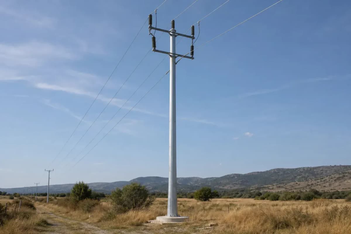
12m 10kV Round Tubular Tangent Tower Slip-Joint
Key Features
- 12 m galvanized round tubular steel structure for 10 kV distribution feeders
- 60 m design span with 1 circuit and 1 conductor per phase
- Slip-joint connection supports 2-section transport and faster field assembly
- Class B wind basis with 15 mm ice allowance for preliminary design
- EPC turnkey range of USD 3,200-5,040 with 1-year warranty
A 12 m, 10 kV round tubular steel tangent tower for 60 m distribution spans, using 1 circuit, 1 conductor per phase, slip-joint assembly, Class B wind loading, and 15 mm ice design basis. EPC turnkey pricing is USD 3,200 to USD 5,040 per installed structure including engineering, procurement, construction, commissioning, and 1-year warranty.
Description
The 12m 10kV Round Tubular Tangent Tower Slip-Joint is a steel round tubular distribution support for 10 kV overhead feeders, 1 circuit, 1 conductor per phase, and a 60 m design span. It uses a 12 m galvanized tubular shaft with a slip-joint connection to simplify transport, accelerate erection, and support straight-line tangent sections that commonly represent 70-80% of structures on overhead distribution routes.
This SOLARTODO power-tower variant is specified for B2B utility, solar-farm, industrial-park, and suburban feeder projects where procurement teams need a repeatable 10 kV pole package with predictable EPC cost from USD 3,200 to USD 5,040 per installed tower. Buyers can View all Power Transmission Tower/Pole products, Configure your system online, or Request a custom quotation for conductor, foundation, wind-zone, and grounding variations.
Technical Specifications
| Parameter | 12 m 10 kV slip-joint tangent tower specification |
|---|---|
| Nominal height | 12 m |
| Voltage class | 10 kV distribution |
| Structure type | Tangent or suspension tower for straight-line sections |
| Material | Hot-dip galvanized steel round tubular shaft |
| Circuits | 1 circuit |
| Conductors per phase | 1 conductor per phase |
| Design span | 60 m typical distribution span |
| Connection type | Slip-joint tubular section connection |
| Wind and ice basis | Class B wind with 15 mm ice design allowance |
| Foundation basis | Reinforced concrete pad or drilled pier, site-specific |
| Design life | 50 years with inspection and galvanizing maintenance |
| Standards basis | IEC 60826, GB 50545, IEEE 738, ASCE 10-15 |
System Architecture
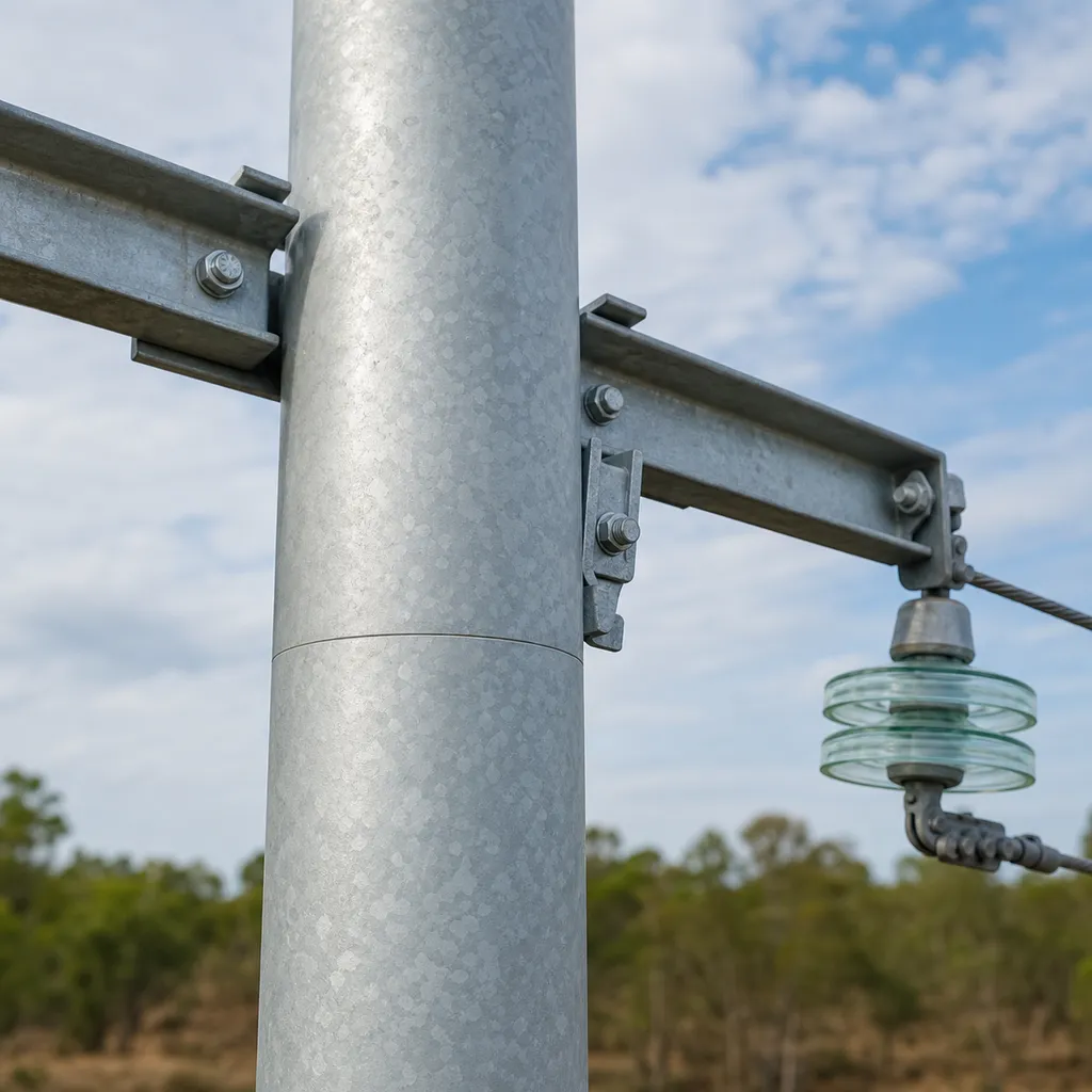
The 12 m structure functions as a tangent support, meaning it is placed on a near-straight feeder alignment rather than at a dead-end, large-angle, or terminal point. In a typical 10 kV distribution line, the tower carries 3 phase conductors on suspension or post-insulator hardware, and its primary loads are vertical conductor weight, transverse wind load, and serviceability deflection under a 60 m span.
The round tubular format replaces multiple bolted angle-steel members with 1 main shaft and fewer exposed edges, which can reduce the visible member count by about 35% compared with a conventional small lattice distribution tower of similar 10 kV service class. The benefit is not a universal weight reduction claim; it is a procurement and installation simplification that depends on steel grade, wind zone, corrosion class, and foundation design.
The slip-joint connection is useful where 12 m full-length shipping is inefficient, because the pole can be fabricated as 2 nested tubular sections and assembled on site with controlled insertion depth. For 10 kV distribution work, this approach reduces bolted splice complexity, keeps erection crews focused on 1 vertical lift sequence, and supports repeatable quality control at 50, 100, or 250 structure procurement volumes.
Standards and Engineering Basis
IEC 60826:2017 defines reliability-based loading and strength principles for overhead lines and is often used as the engineering reference even when the nominal voltage is below 45 kV. For this 10 kV tower, SOLARTODO applies the same discipline to wind, ice, conductor tension, and broken-wire review, while local codes define the final wind speed in m/s and soil parameters in kPa.
IEEE 738-2023 provides the recognized calculation method for current-temperature behavior of bare overhead conductors, which matters because a 10 kV line must coordinate structure design with conductor ampacity, sag, and clearance. For 1 conductor per phase on a 60 m span, the tower geometry should be checked against maximum operating temperature, minimum ground clearance, and local right-of-way requirements.
ASCE 10-15 is used internationally for lattice steel transmission structures, and its load-path concepts remain useful when comparing tubular and lattice alternatives for 10 kV distribution supports. GB 50545 is commonly referenced in China-origin design packages for overhead line engineering, while ISO 1461-style hot-dip galvanizing practice supports a 50-year corrosion-management target when inspection intervals are maintained.
IEA analysis in Electricity Grids and Secure Energy Transitions notes that power grids have become a bottleneck as electrification, EV charging, heat pumps, and renewable interconnection accelerate after 2023. IRENA has also reported that annual renewable power and grid investment must rise substantially before 2030, so standardized 10 kV distribution structures can reduce schedule risk in feeder extension packages.
Materials, Fabrication, and Corrosion Protection
The primary structural member is steel round tube, typically specified around Q460-class steel for tubular poles when project loading requires higher yield strength than ordinary mild steel. Hot-dip galvanizing is used because distribution towers may operate for 50 years in outdoor environments with ultraviolet exposure, rainfall, airborne dust, and seasonal humidity.
Each tower package can include the 12 m pole body, crossarm brackets, pole-top hardware, slip-joint marking, base plate or embedded connection, grounding lug, nameplate, and packing list. For a 50-unit feeder order, SOLARTODO can standardize drilling patterns and jig-controlled bracket locations so that installation tolerances remain consistent across 3-phase conductor positioning.
Quality control should include dimensional inspection, weld visual inspection, zinc coating review, material certificate traceability, and trial assembly for first-article approval. For B2B procurement, this creates 4 practical checkpoints: steel certificate before fabrication, welding inspection before galvanizing, galvanizing inspection before packing, and final packing verification before shipment.
Electrical Configuration
The standard electrical configuration is 1 circuit at 10 kV with 1 conductor per phase, typically using ACSR or AAAC conductors selected by the line designer. Composite polymer insulators are often preferred for 10 kV outdoor feeders because they are lighter than porcelain, have improved impact resistance, and can reduce replacement labor where vandalism or transport breakage is a concern.
Grounding is specified as a tower footing resistance target below 10 ohm for standard service and below 4 ohm in high-lightning areas or sensitive industrial sites. A grounding kit normally includes a down lead, clamp, ground rod or buried conductor, and test point, but final performance depends on soil resistivity measured in ohm-meters and seasonal moisture variation.
OPGW is usually more common on higher-voltage or communication-critical routes, but 10 kV distribution projects may still integrate fiber communication through separate ADSS cable or pole-mounted monitoring equipment. Where feeder automation is required, the pole can support compact sensors, 1 communication cabinet, or 1 low-voltage auxiliary supply within the mechanical limits approved by the project engineer.
Applications
This 12 m 10 kV tangent tower is suited to solar-farm medium-voltage collection roads, industrial-park feeders, rural distribution upgrades, suburban extension lines, and compact utility corridors. In a 1 km straight distribution section using a 60 m average span, a preliminary layout may require about 17 tangent structures before adding angle, terminal, switch, and transformer-pole locations.
For a representative MENA solar farm scenario, assume a 10 kV collection feeder running 1.2 km from inverter station clusters to a step-up transformer bay, with 60 m spans, 15 mm ice allowance used as a conservative mechanical placeholder, and grounding below 10 ohm at each pole. The resulting tangent structure count may be around 20 units, excluding 2 terminal structures and any road-crossing special poles.
The design is also relevant for smart-infrastructure corridors where medium-voltage supply supports lighting, telecom shelters, security cameras, traffic equipment, or pumping stations. Engineers can review related design background at Learn about topic and compare distribution feeder choices with Learn about topic before locking conductor, insulator, and pole-top hardware selections.
EPC Investment Analysis and Pricing Structure
SOLARTODO EPC scope includes engineering, procurement, construction, commissioning, and a 1-year warranty for each 12 m 10 kV tower package. Engineering covers loading confirmation, foundation assumptions, drawings, and bill of materials; procurement covers galvanized steel, insulators, hardware, and packing; construction covers foundation, erection, grounding, and inspection; commissioning covers mechanical checks and energized-line readiness documents.
| Pricing tier | Scope | Unit price range, USD |
|---|---|---|
| FOB Supply | Equipment only, ex-works China | 1,984-3,427 |
| CIF Delivered | Equipment plus ocean freight and insurance | 2,537-4,383 |
| EPC Turnkey | Fully installed, commissioned, and 1-year warranty | 3,200-5,040 |
| Order volume | Indicative discount | Commercial basis |
|---|---|---|
| 50+ towers | 5% | Standardized drawings and repeated steel fabrication |
| 100+ towers | 10% | Consolidated procurement and container loading efficiency |
| 250+ towers | 15% | Project-level production planning and optimized site logistics |
For ROI analysis, the lowest-cost comparison is a basic wood or concrete distribution pole, but those alternatives may require more frequent replacement, heavier handling equipment, or less flexible pole-top customization over a 50-year planning horizon. Against a conventional bolted small lattice tower, the round tubular slip-joint option can reduce erection steps by about 20-30% in repetitive straight-line sections, which can shorten crew time when 50 or more towers are installed under one mobilization.
A representative 100-tower feeder package at an EPC midpoint of USD 4,120 per tower equals about USD 412,000 before volume discount and about USD 370,800 after a 10% volume discount. If standardized slip-joint erection reduces field labor and crane standby by USD 80 per tower compared with a bolted alternative, annualized maintenance and installation savings over a 10-year internal planning period can support a payback period below 5 years for the incremental steel-pole premium.
Payment terms are 30% T/T deposit plus 70% against bill of lading, or 100% irrevocable L/C at sight for qualified bank instruments. Project financing can be discussed for packages above USD 1,000,000, and technical-commercial correspondence should be sent to [email protected] with the line length in km, voltage level, conductor type, wind speed, ice thickness, soil report, and target delivery date.
Procurement and Customization
Procurement teams should specify 7 inputs before quotation: project country, 10 kV nominal voltage, route length in km, conductor type, design wind speed, ice thickness, and foundation soil class. With those 7 inputs, SOLARTODO can size the shaft, confirm the slip-joint overlap, select insulator hardware, estimate packing volume, and align the FOB, CIF, or EPC commercial tier.
Customization options include pole height adjustments from 10 m to 15 m, 1 or 2 circuits, porcelain or composite insulators, standard or high-lightning grounding, and bracket geometry for ACSR, AAAC, or covered conductor applications. The listed 12 m variant remains the baseline where the span is 60 m and the route is primarily straight tangent alignment.
Logistics, Installation, and Commissioning
For export logistics, the slip-joint design allows a 12 m pole to be divided into shorter nested sections, improving container planning and reducing overlength transport exposure. CIF delivered pricing includes ocean freight and insurance, but inland delivery, customs duty, VAT, port demurrage, and remote-site lifting equipment should be evaluated separately for each country and each 50-unit or 100-unit package.
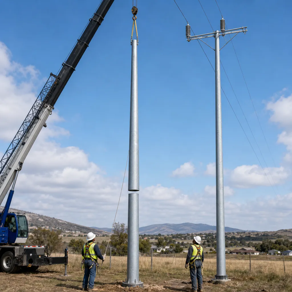
Installation normally follows 6 steps: foundation setting, pole section inspection, slip-joint assembly, vertical erection, pole-top hardware installation, and grounding test. Before energization, the contractor should record pole verticality, bolt torque where applicable, insulator condition, conductor clearance, grounding resistance, and line labeling for each structure number.
Commissioning should not be treated as only a paperwork step, because a 10 kV distribution line depends on mechanical clearance, conductor sag, phase spacing, and grounding continuity. A practical acceptance record includes 1 as-built drawing set, 1 grounding test report, 1 inspection checklist, 1 material certificate package, and 1 warranty start date for every energized line section.
Data Sources and Market Context
The engineering logic in this page references IEC 60826:2017 for overhead-line loading principles, IEEE 738-2023 for conductor thermal rating calculations, ASCE 10-15 for steel transmission-structure design concepts, GB 50545 for overhead-line engineering practice in China-origin projects, IEA 2023 grid-transition analysis, IRENA 2023 energy-transition investment analysis, and NREL PVWatts 2025 as a solar-project context reference.
Because no verified customer deployment reference was supplied for this exact 12 m 10 kV slip-joint tower, this page does not claim any purchased quantity, installed project, certified field result, or customer-approved performance outcome. All prices are indicative USD ranges for 2026 procurement planning and require a site-specific quotation before contract award.
Technical Specifications
| Tower Height | 12m |
| Voltage Rating | 10kV |
| Tower Type | Tangent suspension tower |
| Material | Hot-dip galvanized steel round tubular |
| Number of Circuits | 1circuit |
| Conductor Bundle | 1 x ACSR or AAAC conductor per phase |
| Design Span | 60m |
| Wind/Ice Load | Class B / 15 mm ice |
| Connection Type | Slip-joint tubular connection |
| Foundation | Reinforced concrete pad or drilled pier, site-specific |
| Grounding Target | <10 standard, <4 high-lightning areasohm |
| Design Life | 50years |
| Standards | IEC 60826 / GB 50545 / IEEE 738 / ASCE 10-15 |
Price Breakdown
| Item | Quantity | Unit Price | Subtotal |
|---|---|---|---|
| Galvanized round tubular steel pole | 1 pcs | $1,725 | $1,725 |
| Slip-joint sleeve and connection hardware | 1 pcs | $260 | $260 |
| 10 kV crossarm and bracket set | 1 pcs | $310 | $310 |
| Composite suspension insulator set | 3 pcs | $150 | $450 |
| Grounding system kit | 1 pcs | $500 | $500 |
| Concrete foundation package | 1 pcs | $630 | $630 |
| Engineering and QC documentation | 1 pcs | $285 | $285 |
| Installation and commissioning | 1 pcs | $475 | $475 |
| 1-year warranty and support | 1 pcs | $190 | $190 |
| Total Price Range | $3,200 - $5,040 | ||
Frequently Asked Questions
What is included in the EPC turnkey price for this 12 m 10 kV tower?
Why use a slip-joint round tubular tower instead of a bolted lattice tower?
Is the 12 m tower suitable for all 10 kV distribution lines?
Which standards are used for design review and conductor coordination?
Can SOLARTODO customize the conductor, insulator, or grounding package?
Certifications & Standards


Data Sources & References
- •IEC 60826:2017 Design criteria of overhead transmission lines
- •IEEE 738-2023 Standard for calculating current-temperature relationship of bare overhead conductors
- •IEA Electricity Grids and Secure Energy Transitions 2023
- •IRENA World Energy Transitions Outlook 2023
- •IRENA grid and storage funding analysis 2026
- •NREL PVWatts 2025 solar project context
- •SOLARTODO power-tower configuration data 2026
Interested in this solution?
Contact us for a customized quote based on your specific requirements.
Contact Us