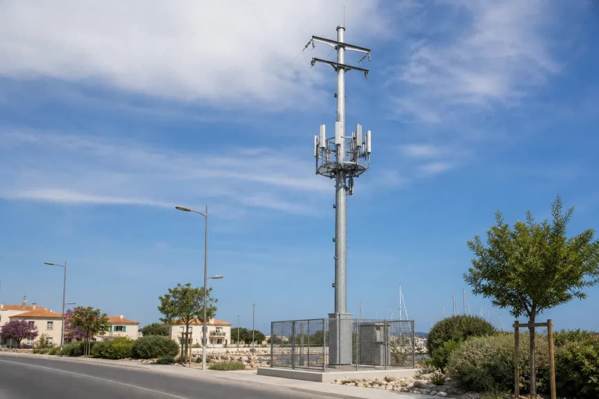
13m Joint-Use Utility Pole - Shared Flanged Telecom Monopole
Key Features
- 13 m steel round flanged telecom pole for shared distribution-area communications corridors
- 37 m/s design wind-speed basis with final TIA-222-H or EN 1993-3-1 structural verification
- 1 antenna platform with 4 antenna mounting positions and 180 kg preliminary tip-load allowance
- Grounding target below 4 ohm with IEC 62305 lightning-protection layout and IEEE Std 81 test basis
- EPC turnkey price range from USD 5,000 to USD 9,233 with 5%, 10%, and 15% volume discounts
13 m flanged steel telecom-only joint-use pole with 1 antenna platform, 4 antenna positions, 37 m/s wind design basis, hot-dip galvanizing, and EPC turnkey pricing from USD 5,000 to USD 9,233.
Description
The 13m Joint-Use Utility Pole Distribution Telecom Shared Flanged is a 13 m steel round telecom monopole for shared distribution-area communications, designed for 4 antennas on 1 top platform and a 37 m/s basic wind-speed basis. The flanged base, hot-dip galvanized steel shaft, lightning system below 4 ohm, and 30-year design life make it suitable for urban 4G/5G fill-in coverage, fiber backhaul, CCTV, and smart-infrastructure telemetry without adding any electrical conductors or power-line hardware.
Technical Specifications
This configuration is a telecom-only joint-use utility pole, meaning it can share a right-of-way, campus, roadside, depot, or distribution corridor with other civil infrastructure, but it does not carry 1 kV, 11 kV, 33 kV, or any energized overhead line. SOLARTODO specifies the structure as a 13 m round steel monopole with a flanged connection, 1 antenna platform, 4 antenna mounting positions, and a preliminary 180 kg total tip-load allowance for antennas, remote radio units, cable tray, warning light, and maintenance accessories.
| Parameter | 13m flanged shared telecom pole value |
|---|---|
| Overall height | 13 m |
| Pole type | Joint-use telecom monopole, telecom only |
| Material | Steel round pole, hot-dip galvanized |
| Connection | Flanged base with anchor bolts |
| Antenna platform levels | 1 level |
| Antenna capacity | 4 antennas |
| Design wind speed | 37 m/s |
| Preliminary total tip load | 180 kg |
| Design life | 30 years with scheduled inspection |
| Foundation concept | Reinforced concrete pad or drilled pier, about 6 m3 preliminary volume |
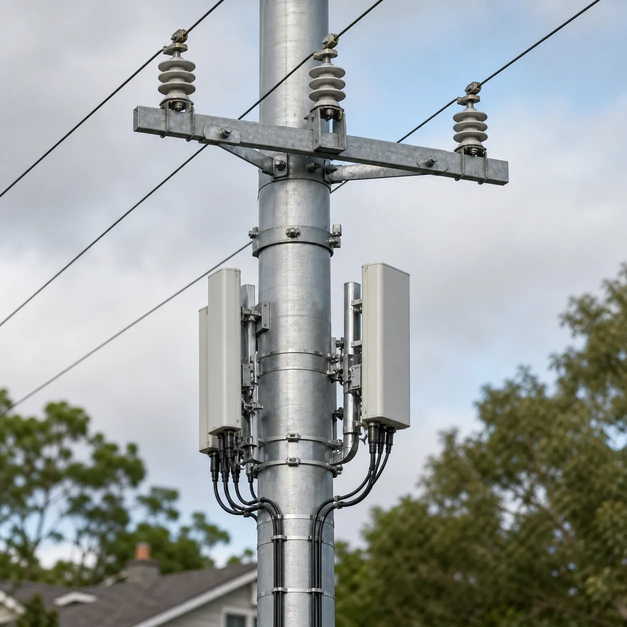
The structural basis should be checked against ANSI/TIA-222-H, which defines minimum loading and design criteria for antenna supporting structures and appurtenance mounting systems, and against EN 1993-3-1 where Eurocode 3 tower and mast practice is required. For a 37 m/s wind-speed requirement, SOLARTODO treats the published configuration as a quotation-stage design and recalculates gust factor, exposure category, topographic factor, antenna projected area, and foundation overturning moment after receiving 1 site coordinate, 1 geotechnical note, and the final 4-antenna schedule.
The pole shaft is specified as hot-dip galvanized steel with marine-grade coating options, using ISO 1461:2022 as the reference for fabricated iron and steel galvanized coatings. Compared with a conventional 13 m lattice telecom tower, the round monopole form can reduce visible plan footprint by about 60-75% and eliminate 3 or 4 corner legs, which is useful in roadsides, warehouse yards, water-treatment sites, metro depots, and industrial parks where land allocation is measured in square meters rather than hectares.
System Architecture
The system architecture has 5 physical layers: the reinforced concrete foundation, the flanged anchor-bolt cage, the galvanized steel pole shaft, the 1-level antenna platform, and the earthing/lightning network. A typical 13 m package includes 1 pole body, 1 flange plate, 1 anchor-bolt set, 1 cable tray route, 1 external ladder or service step arrangement where permitted, 1 anti-climbing barrier around the 3 m zone, and 1 lightning air terminal connected to a down conductor and buried earth electrodes.
The telecom payload can support 4 panel antennas, 1 compact microwave dish in many layouts, GPS timing equipment, aviation warning lighting, and weatherproof radio enclosures, subject to the 180 kg preliminary tip-load limit and final wind-area calculation. Cable routing normally reserves 13 m of vertical tray or internal conduit path, with separate bend radii for coaxial, fiber, and DC power cables so that the RF system, backhaul link, and monitoring cabinet can be commissioned in 1 coordinated site visit.
Lightning protection follows the practical intent of IEC 62305 for air termination, down-conductor continuity, bonding, and surge-risk reduction, while grounding measurement can reference IEEE Std 81-2025 for soil resistivity and earth-system test methods. The quotation target for this product is a grounding resistance below 4 ohm, but high-resistivity desert, rock, or reclaimed coastal soil may need 2-6 additional electrodes, conductive backfill, or a ring-earth conductor to reach the measured value.
Applications
The 13 m shared flanged telecom pole is intended for small-cell densification, private LTE/5G networks, fiber backhaul handoff points, municipal camera coverage, industrial IoT gateways, solar-farm communications, and utility-yard security systems. View all Telecom Tower products if a project needs a 10 m, 15 m, or 18 m pole family rather than a single 13 m shared platform.
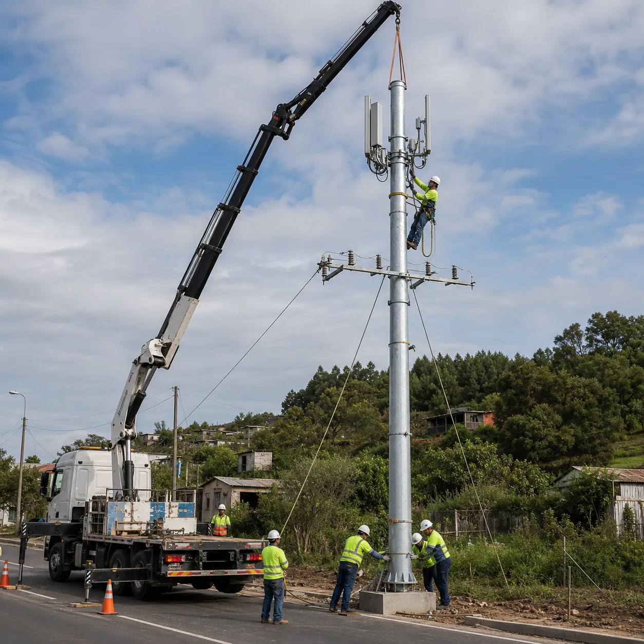
For a representative MENA solar farm scenario, a developer may place 6 units of 13 m telecom-only poles along a 2 km perimeter to support 24 directional antennas, CCTV uplinks, and SCADA backhaul without installing separate 18 m lattice towers at each camera cluster. At an EPC midpoint of about USD 7,117 per pole, the 6-pole communications layer represents about USD 42,702 before local taxes, radio equipment, or long-distance fiber trenching, and it can simplify civil works by using a repeated flanged foundation detail.
For city districts and logistics parks, the pole is also appropriate where 4G/5G coverage, Wi-Fi backhaul, public-address equipment, and security cameras must share a narrow site. The configuration is not a power distribution pole: SOLARTODO excludes insulators, crossarms for conductors, reclosers, transformers, and any 50/60 Hz overhead power circuit from this telecom-tower product line, which keeps the design scope aligned with TIA-222-H antenna-support practice rather than power-line standards.
Engineering, Procurement, and Quality Control
Engineering deliverables normally include 1 general arrangement drawing, 1 foundation recommendation, 1 anchor-bolt layout, 1 antenna mounting schedule, 1 grounding diagram, 1 galvanizing and inspection note, and 1 packing list. Procurement deliverables include steel material certificates, zinc-coating inspection records, bolt grade certificates, welding inspection records when applicable, and dimensional checks for the flange, bolt circle, pole straightness, and platform interface.
Quality control is based on 4 stages: raw steel confirmation, fabrication inspection, hot-dip galvanizing inspection, and pre-shipment fit-up review. For B2B buyers, the practical procurement value is repeatability: a 13 m flanged design can be standardized across 50, 100, or 250 sites, while still leaving project-specific variables such as soil bearing capacity, wind exposure, antenna brand, and cabinet layout open for final engineering.
Global market drivers support this product category because telecom densification and renewable-energy site digitalization both require more edge communication points. IEA Renewables 2025 projects about 4,600 GW of renewable power additions between 2025 and 2030, and IRENA 2025 reports 582 GW of renewable capacity additions in 2024, creating many new sites that need monitoring, metering, surveillance, and backhaul rather than only generation equipment.
EPC Investment Analysis and Pricing Structure
EPC turnkey service includes 5 work packages: engineering, procurement, construction, commissioning, and 1-year warranty support. SOLARTODO’s EPC scope can include anchor-bolt cage delivery, foundation construction, pole erection, grounding test, antenna-platform installation, cable-tray installation, visual inspection, commissioning records, and handover documentation; radio equipment, carrier SIM plans, tower leasing permits, and local utility approvals are treated as separate 1-line exclusions unless written into the contract.
| Pricing tier | Commercial scope | Price range in USD |
|---|---|---|
| FOB Supply | Equipment only, ex-works China | USD 3,100-6,278 |
| CIF Delivered | Equipment, ocean freight, and insurance | USD 3,964-8,028 |
| EPC Turnkey | Installed, commissioned, and 1-year warranty | USD 5,000-9,233 |
| Order volume | Discount basis | Example saving against USD 7,117 midpoint |
|---|---|---|
| 50+ poles | 5% | USD 356 per pole |
| 100+ poles | 10% | USD 712 per pole |
| 250+ poles | 15% | USD 1,068 per pole |
ROI should be assessed against avoided site rentals, reduced civil footprint, fewer separate tower foundations, and lower repeated mobilization cost. If a conventional alternative uses 1 small lattice tower and 1 separate camera mast per site at about USD 9,500 combined installed cost, this 13 m shared telecom pole at the USD 7,117 EPC midpoint can reduce installed civil-structure cost by about 25% and save about USD 2,383 per site before radio equipment.
For a 100-site program, the 10% volume discount can reduce a USD 711,700 midpoint structure budget by about USD 71,170, while standardization may also reduce drawing review, foundation formwork variation, and spare-anchor logistics. A simple payback model using USD 2,383 avoided alternative cost per site and USD 250 annual inspection efficiency per site gives immediate capital avoidance plus about USD 25,000 annual O&M simplification across 100 poles, subject to buyer-specific labor rates and local permitting costs.
Payment terms are normally 30% T/T deposit plus 70% against B/L copy, or 100% irrevocable L/C at sight for approved buyers, with project financing discussion available for qualified projects above USD 1,000,000. Procurement teams can Configure your system online for a first-pass quantity model or Request a custom quotation with site coordinates, 37 m/s wind basis, antenna dimensions, soil report, delivery port, and required Incoterms; direct commercial contact is [email protected].
Standards and Compliance Notes
The 13 m telecom pole is normally specified with TIA-222-H or EN 1993-3-1 structural design checks, ISO 1461 galvanizing, IEC 62305 lightning protection, and IEEE Std 81 grounding test references. Buyers that require CE-related documentation, local building authority review, or carrier-specific mount certification should provide the required 2 or 3 forms at quotation stage so SOLARTODO can align drawings, inspection reports, and nameplate data before production.
NREL’s PVWatts Version 8.5.2 uses 30 years of weather data for solar production variability, and that same 30-year engineering mindset is relevant when telecom poles support solar-farm monitoring systems with no tolerance for repeated outage visits. For broader system planning, Learn about topic pages can be used to connect telecom structures with PV, storage, smart lighting, and security-system engineering assumptions across 8 public product families.
Buyer Selection Guidance
Choose the 13 m flanged version when the project needs fast installation, bolted base replacement, containerized shipping, and repeatable foundation templates across 50 or more sites. Choose a taller 15-18 m monopole when Fresnel clearance, microwave path geometry, or nearby roof clutter requires additional elevation; choose a lattice tower only when large antenna projected area, multiple microwave dishes, or heavy top loads exceed the 180 kg preliminary allowance.
Before purchase, buyers should confirm 7 inputs: final site coordinates, design wind speed, exposure category, antenna count, antenna dimensions, cable count, and soil bearing capacity. SOLARTODO can then issue a project-specific drawing package, EPC schedule, and itemized USD quotation that keeps telecom scope separate from power-line scope and keeps all 4 antennas within the approved structural and grounding design basis.
Technical Specifications
| Tower Height | 13m |
| Tower Type | joint_use_pole |
| Material | steel_round |
| Application | distribution_telecom_shared |
| Connection Type | flanged |
| Antenna Platforms | 1levels |
| Antenna Capacity | 4antennas |
| Design Wind Speed | 37m/s |
| Total Tip Load | 180kg |
| Foundation Type | Reinforced concrete pad or drilled pier with flanged anchor-bolt cage |
| Corrosion Protection | Hot-dip galvanized / Marine grade optional |
| Design Life | 30years |
| Standards | TIA-222-H / EN 1993-3-1 / ISO 1461 / IEC 62305 |
Price Breakdown
| Item | Quantity | Unit Price | Subtotal |
|---|---|---|---|
| Q355 hot-dip galvanized steel round pole shaft | 1 pcs | $2,700 | $2,700 |
| Steel antenna platform, installed | 1 pcs | $800 | $800 |
| External ladder and safety rail, 13 m allowance | 13 pcs | $15 | $195 |
| Cable tray system, 13 m allowance | 13 pcs | $10 | $130 |
| Lightning protection system with grounding interface | 1 pcs | $500 | $500 |
| Aircraft warning light set | 1 pcs | $300 | $300 |
| Reinforced concrete foundation, preliminary 6 m3 | 6 pcs | $300 | $1,800 |
| Steel pole installation and lifting allowance | 1 pcs | $360 | $360 |
| Engineering drawings and QC documentation | 1 pcs | $350 | $350 |
| Commissioning and grounding test support | 1 pcs | $385 | $385 |
| 1-Year warranty and remote support | 1 pcs | $250 | $250 |
| Total Price Range | $5,000 - $9,233 | ||
Frequently Asked Questions
Can this 13 m joint-use pole carry electrical distribution conductors?
What is included in the EPC turnkey price range of USD 5,000-9,233?
How is the 37 m/s wind-speed requirement verified?
What antenna load can the standard 13 m configuration support?
What maintenance is expected over a 30-year design life?
Certifications & Standards



Data Sources & References
- •Telecommunications Industry Association, ANSI/TIA-222-H publication notice, 2017, https://standards.tiaonline.org/news-media/press-releases/tia-announces-publication-tia-222-h-standard-antennas-and-supporting
- •NREL PVWatts Calculator Version 8.5.2, 2025, https://pvwatts.nrel.gov/version_8.php
- •IEA Renewables 2025, renewable electricity forecast, https://www.iea.org/reports/renewables-2025/renewable-electricity
- •IRENA Renewable Power Generation Costs in 2024, 2025, https://www.irena.org/Publications/2025/Jun/Renewable-Power-Generation-Costs-in-2024
- •ISO 1461:2022 hot dip galvanized coatings, https://www.iso.org/standard/81435.html
- •IEC 62305 lightning protection series, 2026, https://webstore.iec.ch/en/publication/6797
- •IEEE Std 81-2025 grounding measurement guide, https://standards.ieee.org/ieee/81/11218/
Interested in this solution?
Contact us for a customized quote based on your specific requirements.
Contact Us