
Summary
For a proposed Santiago installation of the SOLARTODO classic twin-arm bronze smart streetlight, request photometric distribution data and electrical measurements matched to the actual offered luminaires, optics, drivers and operating settings. Have the responsible designer use that evidence with surveyed geometry and locally established acceptance criteria to compare twin-arm layouts. Approve final spacing only after a representative installation verifies the selected arrangement and material discrepancies are resolved.
The catalog establishes the appearance and scope of smart-classic-twin-bronze, not numerical lighting performance, electrical capacity or compliance. Santiago is solely a proposed site; no installation or measured result there is established.
Key Takeaways
- Define the lighting task: Have the site designer document the surfaces, geometry, obstructions and locally applicable acceptance criteria before comparing layouts.
- Match evidence to the offer: Ask the supplier for photometric distribution data and electrical reports identifying the offered luminaire, optics, driver and settings before selecting equipment.
- Calculate both arms together: Have the lighting designer model each luminaire’s position, orientation and contribution, checking weak areas and overlap before proposing spacing.
- Separate electrical loads: Require the supplier to distinguish lighting input from auxiliary equipment and charging loads so the electrical designer can assess the proposed supply.
- Verify the selected arrangement: Agree on field measurements, operating conditions and discrepancy handling before using a representative installation to support final layout approval.
- Control substitutions: Require the supplier and designer to review changes to optics, drivers, output settings or mounting geometry and revise affected evidence before acceptance.
FAQ
What evidence should determine luminaire selection?
Use photometric distribution data and electrical measurements for the actual offered luminaire, optic, driver and operating setting. The designer must assess those results against the surveyed lighting task and agreed local criteria.
When can the buyer approve final pole spacing?
Approve final spacing after matched configuration data supports the site calculations, the electrical design supports the intended loads, and representative field measurements meet the agreed criteria with material discrepancies resolved.
How should the twin arms be evaluated?
Model both luminaires in their proposed positions and orientations. Check their combined contribution across the required surfaces, including overlap and weak areas; the twin-arm appearance alone does not establish coverage.
Which electrical measurements should the supplier provide?
Request input power, voltage, current, power factor and relevant waveform or harmonic information under identified supply and control conditions. Separate lighting consumption from auxiliary equipment and EV charging loads.
What changes require renewed verification?
Review changes to the luminaire, optic, driver, output setting, orientation or mounting geometry. Obtain revised reports, calculations or field measurements wherever the change affects the basis of acceptance.
Do the U.S. references establish compliance in Chile?
No. DOE and FEMP provide external research, purchasing and measurement context. The responsible local designer and authority must establish the requirements for the proposed Santiago site.
What does the catalog establish, and is a product PDF available?
The supplied catalog establishes the smart-classic-twin-bronze appearance and listed scope, without numerical performance or compliance. No authoritative product PDF, PDF URL or page-specific extract was supplied.
Is Santiago an existing installation reference?
No. Santiago is solely a proposed site. The supplied evidence establishes no customer deployment, surveyed street or measured operating result there.
Product scope and evidence authority
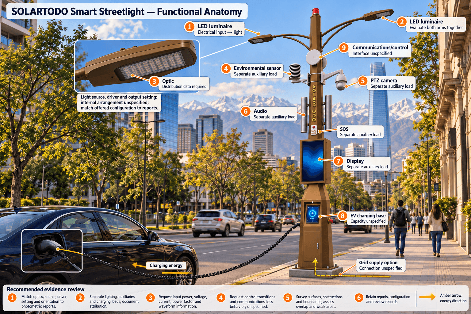
The supplied versioned extraction of the SOLARTODO smart streetlight catalog, city-catalog-2026-11-01-v1, identifies smart-classic-twin-bronze as a bronze polygonal pole with two curved luminaire arms, PTZ camera, environmental sensor, display, audio/SOS and integrated EV charging base. Grid-fed lighting and modular communications/control are catalog options.
The selected appearance excludes a drone hangar, robot, wind turbine and wrapped CIGS photovoltaic surface. The catalog establishes no numerical height, power, charging rate, light output, distribution, efficiency, standard compliance or installed-project performance.
Use the internal smart streetlight product page for product navigation. For technical review, request an authoritative product PDF with its model, revision, relevant pages and operating conditions. None was supplied, so no PDF specification or page citation can be given. An authoritative product PDF would take precedence over conflicting catalog descriptions for the configuration and conditions it actually covers; external DOE and FEMP guidance cannot fill missing product specifications.
Establish the site criteria
Commission a survey of the proposed evaluation area. Record the carriageways, pedestrian surfaces, crossings, access points, boundaries and obstructions that actually exist, together with proposed mounting locations and available supply information.
Have the responsible local designer and authority establish the lighting requirements and acceptance methods. Identify where horizontal illumination, vertical illumination, uniformity, glare or unwanted light needs assessment. These are proposed design tasks, not documented conditions or legal requirements for a particular Santiago street.
Keep height, arm geometry, orientation, tilt, setback and spacing provisional until the calculations support a selection. Agree on assessment limits before comparing supplier proposals so an attractive average value cannot conceal unacceptable weak areas.
Obtain configuration-specific test evidence
Photometric evidence
Ask the supplier for a complete photometric report and calculation-ready distribution data identifying the offered luminaire, optic, light source, driver, output setting and tested orientation. Request the laboratory identity, test date, measurement method, test conditions and uncertainty. Confirm how the tested units correspond to the luminaires offered on both arms.
The supplied FEMP exterior-lighting guidance, updated in June 2023, names IES LM-79-08 for electrical and photometric measurements of solid-state lighting products and IES LM-50-13 for photometric measurements of roadway and street-lighting installations. These are measurement-method references in U.S. federal purchasing guidance, not evidence that this product was tested or certified. The project must separately establish the applicable methods and editions.
If reduced-output operation is proposed, request evidence applicable to that state before relying on it in the design. Full-output results do not verify a reduced-output setting, and data for another optical assembly does not establish the offered assembly’s distribution.
Electrical evidence
Request measured input power, supply voltage, current, power factor and relevant waveform or harmonic information. Reports should identify supply conditions, stabilization conditions, control state and the measurement boundary, including whether driver losses and control equipment are included.
Require separate load information for lighting, camera, environmental sensor, display, audio/SOS, communications and EV charging. Where direct separation is unavailable, request a documented attribution method. Whole-pole consumption alone cannot establish luminaire efficacy or lighting-only savings.
For the integrated charging base, request its electrical specification and proposed simultaneous-load conditions. Its charging rate and shared-supply capacity remain unknown. The electrical designer needs documented loads before selecting service capacity.
If the layout depends on controls, request evidence of the offered system’s state transitions and communications-loss behavior. These are proposed verification requests; the catalog does not establish those behaviors.
The DOE connected-lighting overview describes a test bed focused on electrical performance rather than reproducing real-world lighting environments. This supports keeping electrical assessment distinct from site illumination verification. It does not demonstrate the selected product’s performance or savings.
Compare layouts, then verify the selection
Have the lighting designer calculate candidate arrangements using the same surveyed geometry, criteria and documented equipment configuration. Model both arms at their proposed positions, orientations and settings. Review the required surfaces, overlap, weak areas and relevant adjacent boundaries rather than selecting spacing from nominal wattage.
Keep measured inputs separate from assumptions, including surface characteristics and any allowance for changes over time. Compare only layouts whose assumptions and operating conditions are explicit. A layout that lacks suitable distribution data remains a proposal, even if its pole arrangement appears plausible.
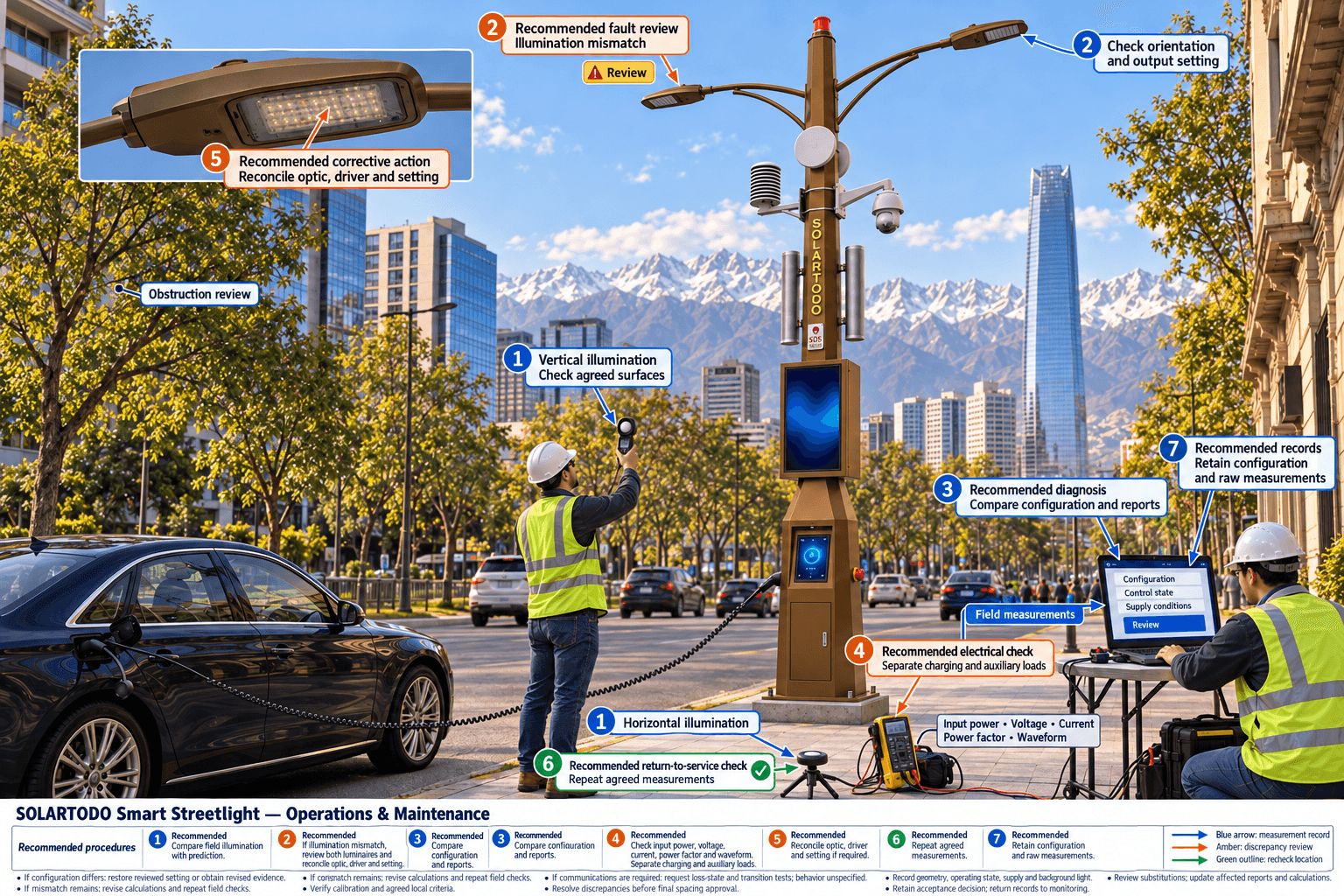
Before a representative installation, agree on measurement locations, instrument calibration evidence, operating states, background-light treatment and discrepancy review. Record actual mounting geometry, settings and supply conditions during measurement. Investigate material differences between prediction and observation before extending the arrangement.
If an optic, driver, output setting or mounting arrangement changes, have the designer identify which calculations and measurements are affected. Acceptance should remain tied to the configuration actually evaluated.
Buyer decision and handover
The following are proposed procurement gates, not manufacturer guarantees or established local requirements:
- Equipment selection: The supplier identifies the offered configuration and supplies reports applicable to it; the designer determines whether it suits the lighting task.
- Provisional layout: Site calculations support the locally agreed criteria, and the electrical assessment covers the intended operating loads.
- Final spacing: Representative field evidence supports the selected arrangement, with discrepancies and exceptions recorded and resolved by the responsible reviewers.
- Handover: Retain configuration identifiers, reports, calculation inputs, raw measurements, control settings and the acceptance decision. Assign responsibility for reviewing later substitutions.
Any tolerance, observation period or operating schedule added to the evaluation protocol remains a proposed assumption until approved for the project. No hypothetical lux, spacing, efficacy or power value is needed to make this proposal appear complete.
The remaining selection inputs are the site survey, locally applicable criteria, authoritative product documentation and configuration-specific test reports. Without them, the supplied evidence cannot determine output, mounting height, spacing, service capacity or a final bill of materials. Commercial enquiries can proceed through contact, with technical acceptance conditional on those inputs and the agreed verification.
References
- SOLARTODO smart streetlight catalog: supplied extraction city-catalog-2026-11-01-v1; model smart-classic-twin-bronze; catalog appearance and scope only.
- DOE: Connected Lighting Systems: supplied extract describing connected-lighting research and electrical evaluation infrastructure; external U.S. context, not product verification.
- FEMP: Purchasing Energy-Efficient Exterior Lighting: supplied extract of U.S. federal acquisition guidance updated in June 2023, including named measurement methods. Its purchasing thresholds and financial examples are not Chilean requirements or Santiago forecasts.
Proposed Equipment
- SOLARTODO classic twin-arm bronze smart streetlight, catalog reference smart-classic-twin-bronze
- Bronze polygonal pole with two curved luminaire arms
- PTZ camera
- Environmental sensor
- Display
- Audio/SOS equipment
- Integrated EV charging base
- Optional grid-fed lighting
- Optional modular communications/control equipment